Motors with 3mm bullet plug connectors should fit OK in the Arm tubes. But for greater clearance, the builder may consider using 2mm bullet plugs.
The motor wires should be only long enough to be placed inside the Arm tube. Wire slack is taken up by withdrawing excess wire length inside the Fuselage Body.
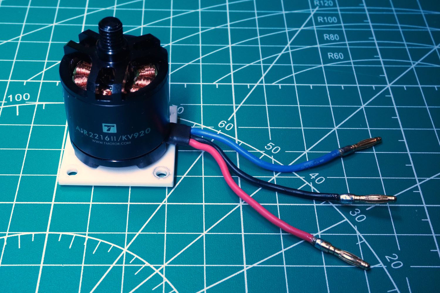
Here the motor wires are cut to 50mm length and replaced with 2mm bullet connectors.
Motors with “spin-on” propellers must be installed on arms in the proper positions for their propeller rotation.
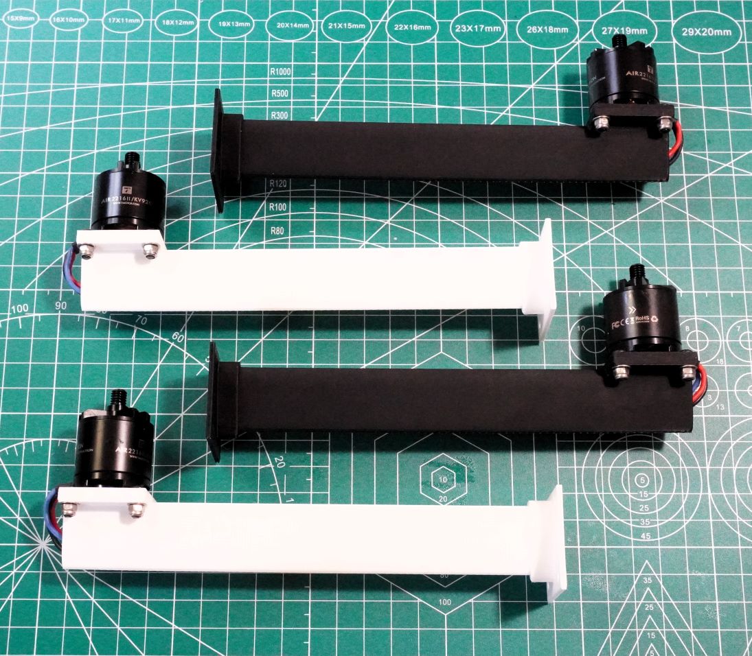
In this example, I use white arms for the forward arms, and black arms for the rear arms.
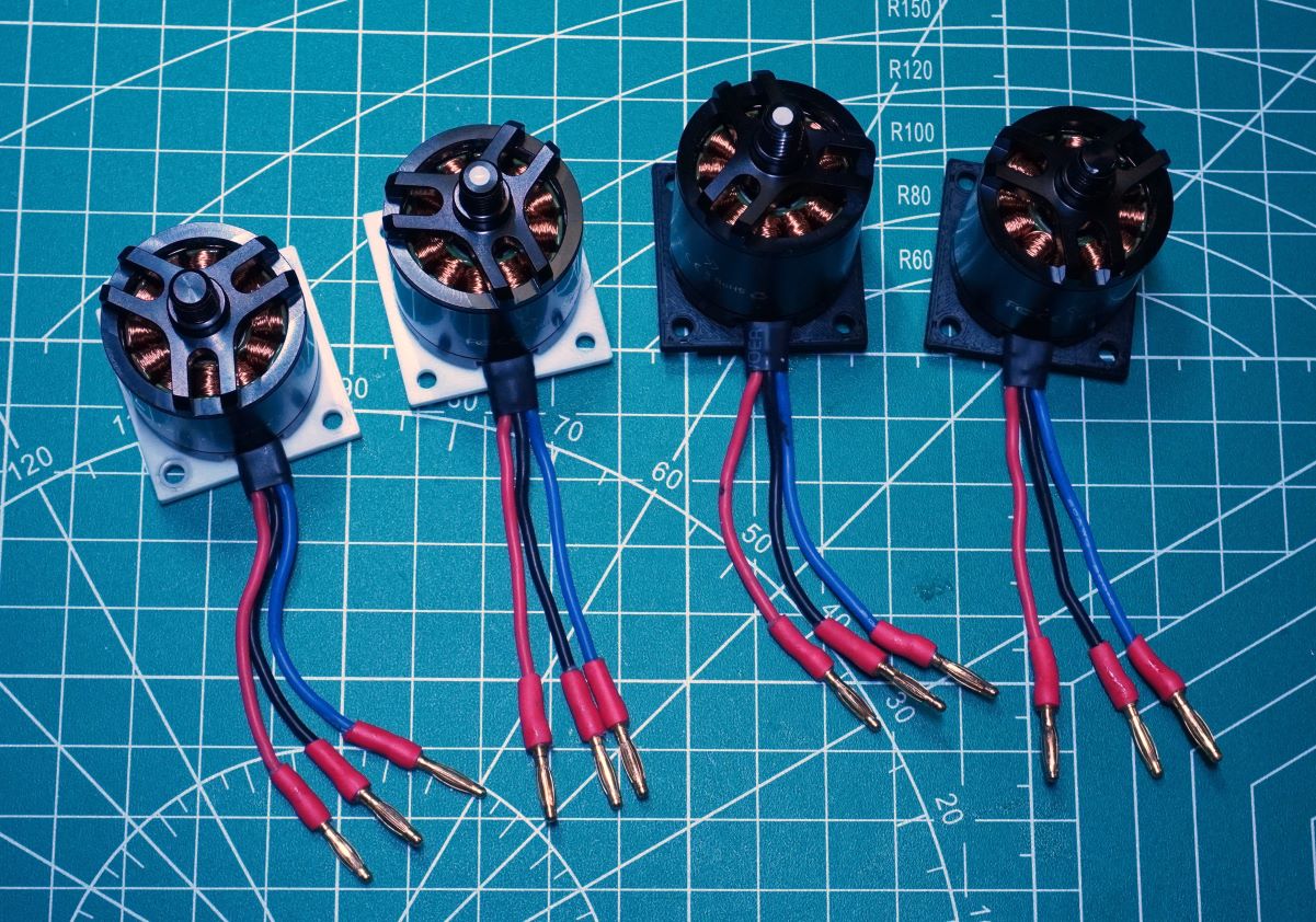
Here the white motor plates are for the two forward arms, and the black are for the two rear arms. Note the silver and black dots on the top of motor shaft that indicate motor direction. A clockwise and counter-clockwise motor are on both the black and white mounts.
Here the motors and Motor Mount Plates are attached to the Arms.
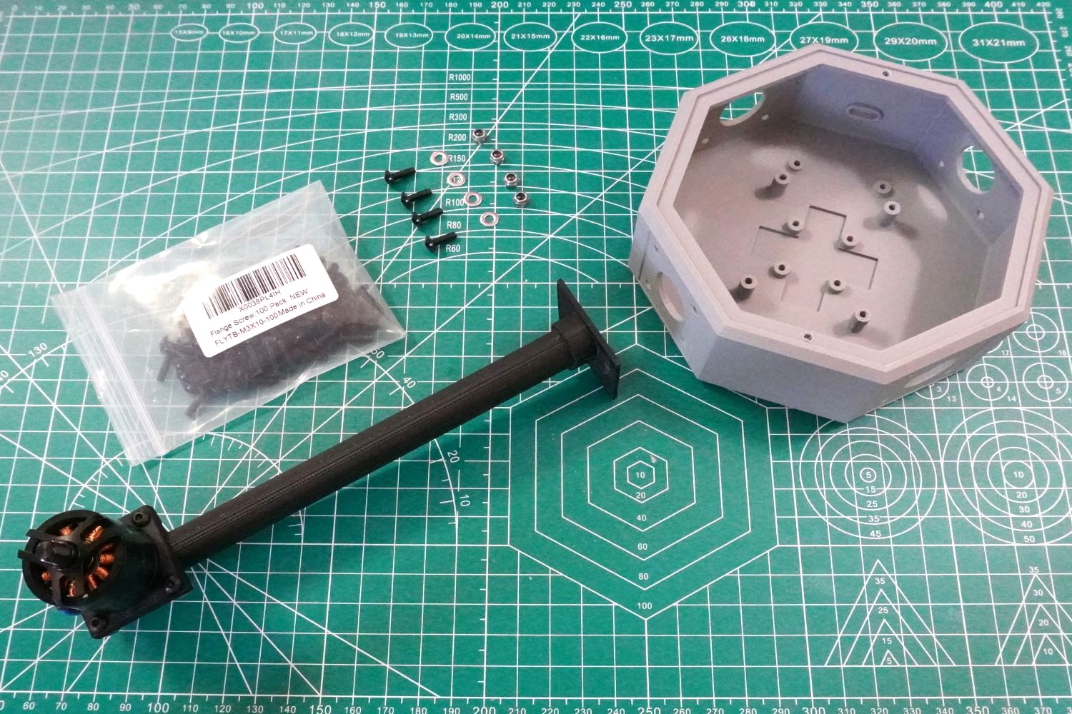
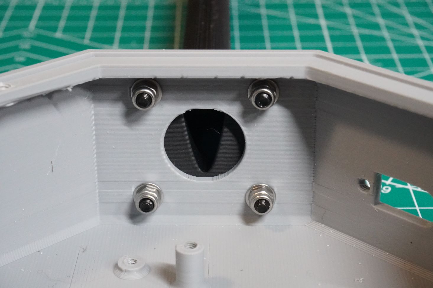
Arms attach to the Fuselage Body with four 10mm long M3 flange head screws.
Washers and nylock nuts are recommended.
Here is the inside of the Fuselage Body. The 10mm M3 flange head screws, washers and nylock nuts are visible.