
The builder must decide on the assembly methods that best suit them. These illustrated examples show only some of the possible ways to do the assembly.
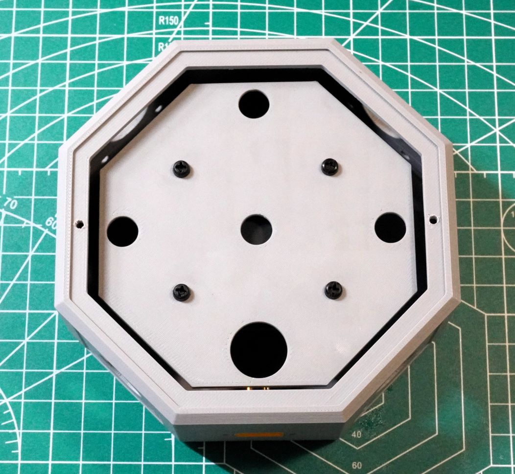
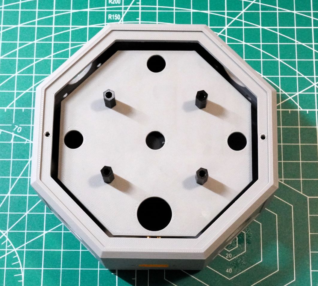
The Fuselage Body has 12 holes in the bottom and 2 holes on the rim to accept M3 screws.
Due to differences in 3D printing tolerances, these holes are slightly undersized.
To accept an M3 screw, the holes must first be drilled out to 2.5mm, and then threaded with a M3 tap.
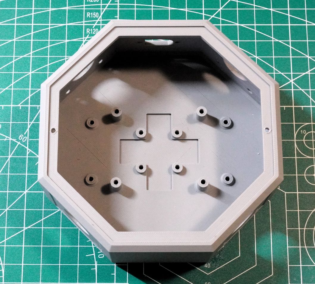
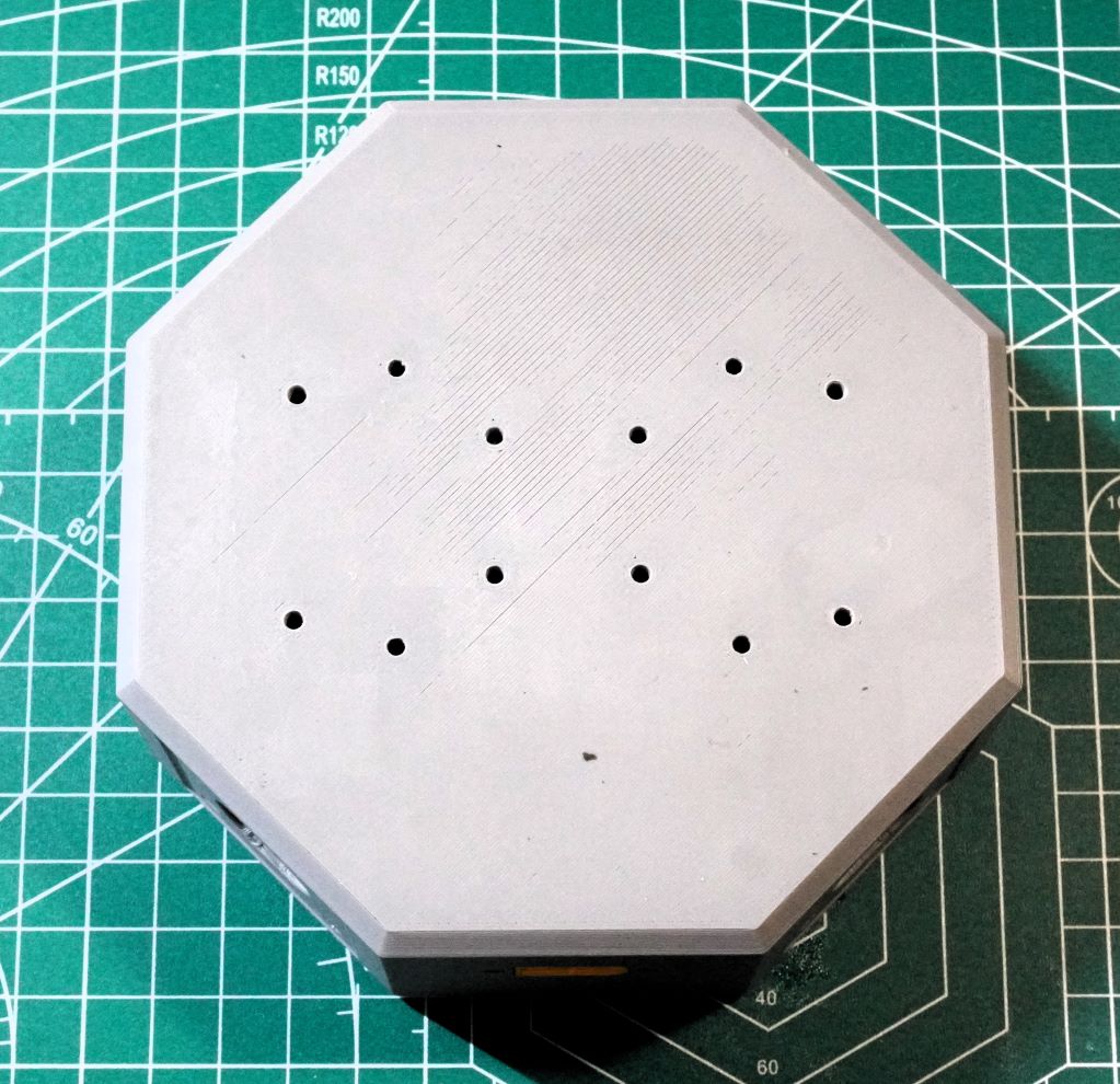
The twelve holes go though to the bottom.
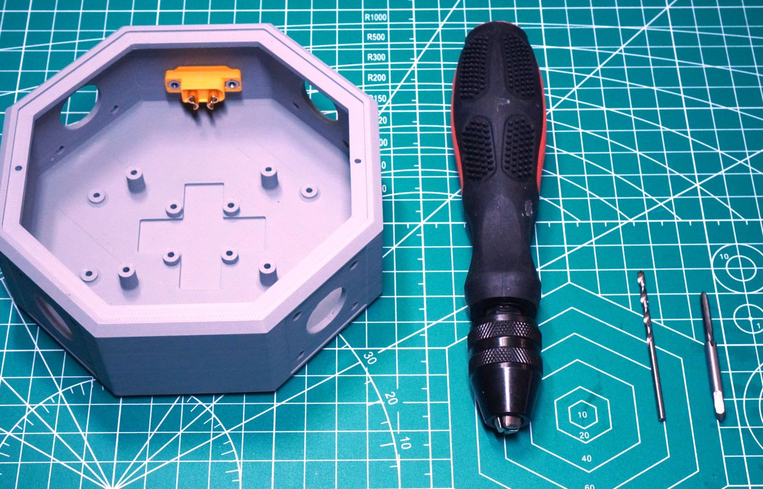
A handheld pin-vice with a 2.5mm drill bit and M3 tap are good tools for preparing the fuselage holes.
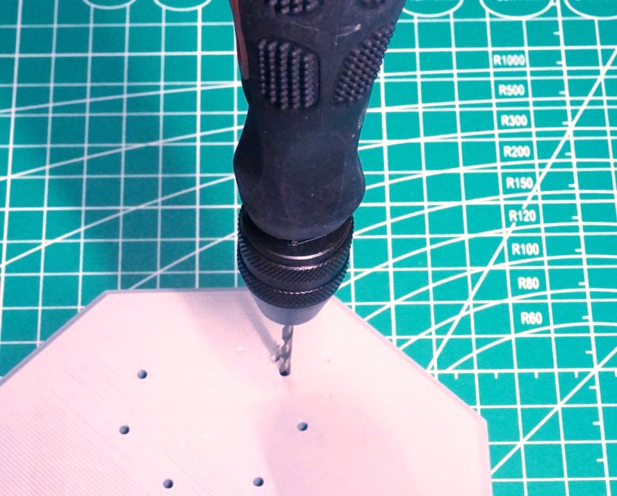
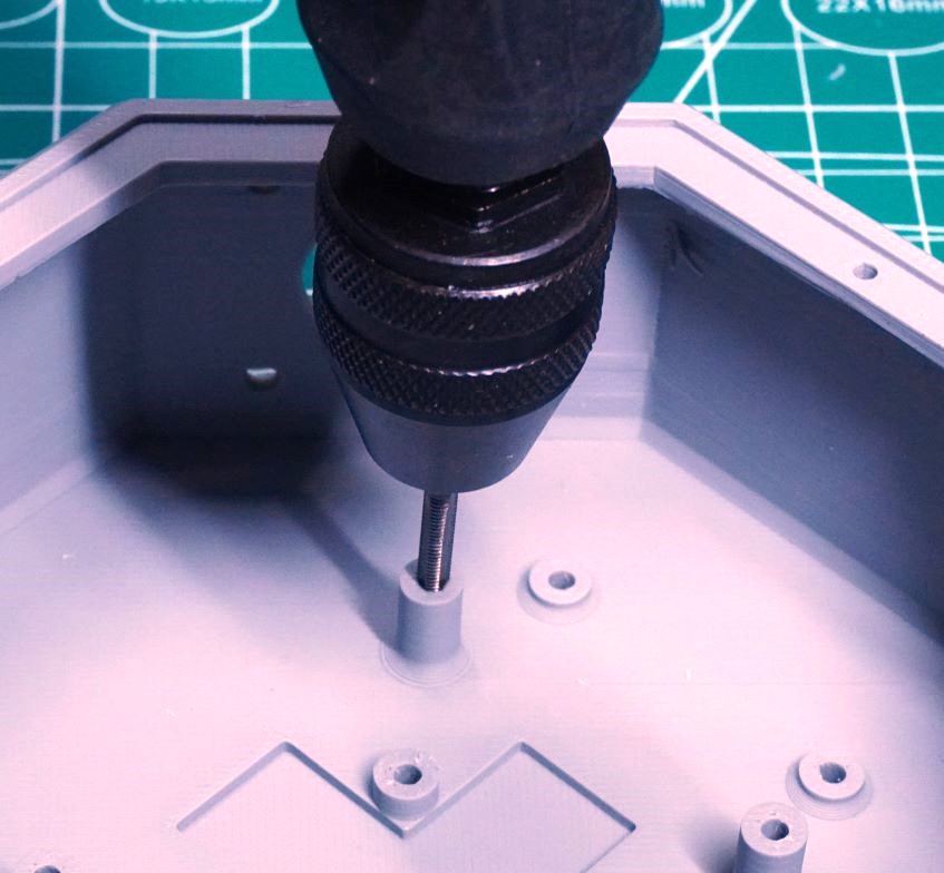
A pin-vice can be used to drill out the bottom fuselage holes with a 2.5mm drill bit.
After the hole is enlarged to 2.5mm, a M3 tap can thread the hole to accept an M3 screw.
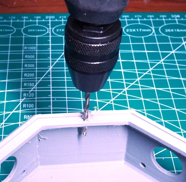
The holes on the fuselage lip must also be enlarged to 2.5mm before they are tapped.
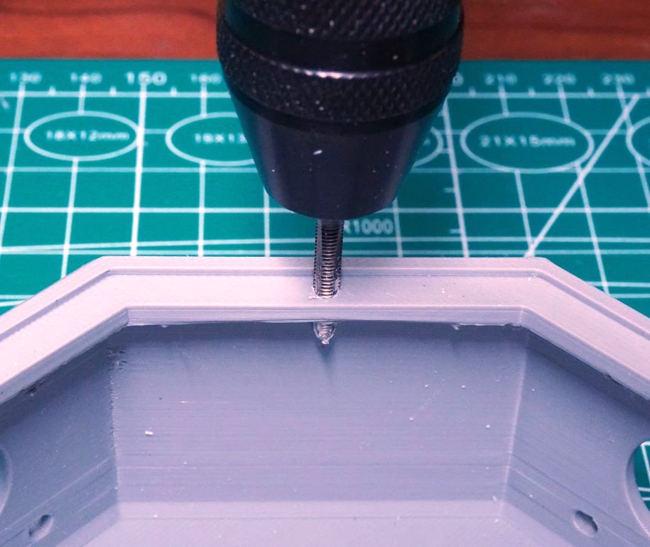
After the hole is enlarged to 2.5mm, it can be tapped to have M3 threads.
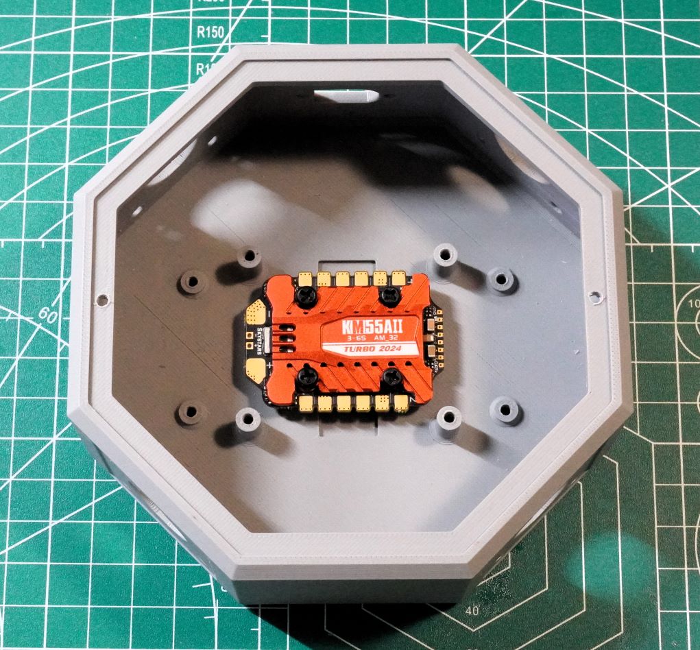
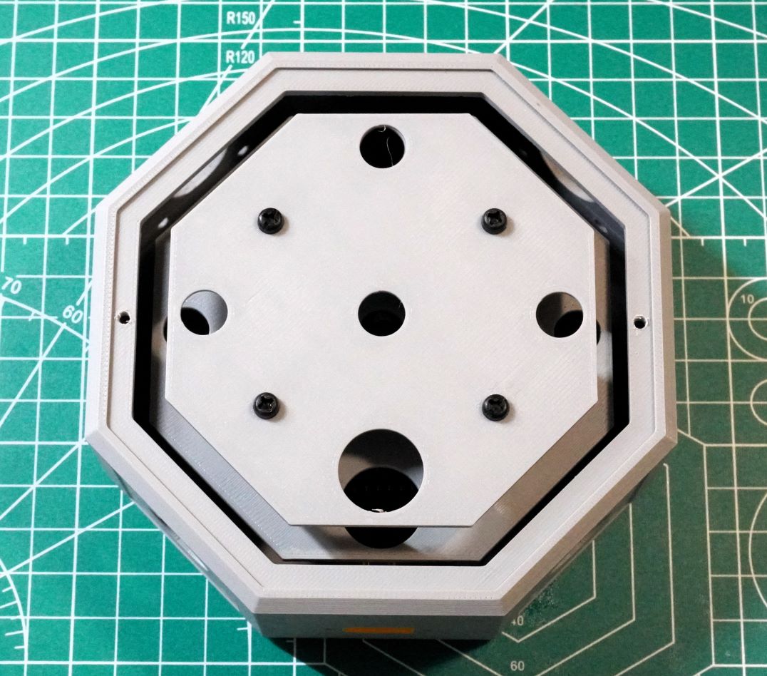
With the holes drilled and tapped, an ESC with a 20×20 mount pattern can be secured with screws.
Here nylon screws are used to avoid possible electrical shorting with the electronics.
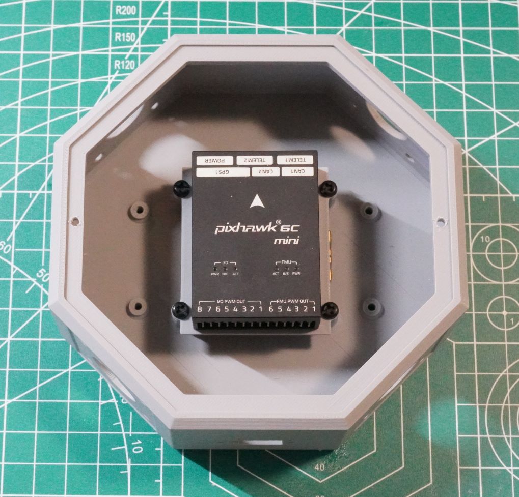
Here is an example of a Holybro Pixhawk 6C Mini on the Flight Controller Tray.
To have proper clearance over the ESC, it may be necessary to place washers between the Flight Controller Tray and the Fuselage mounts. In this example, none were required.
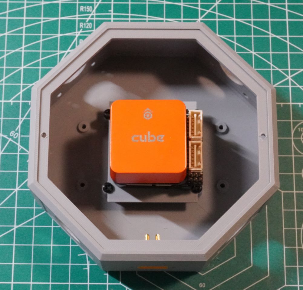
Here is an example of a CubePilot Orange Cube and Mini Carrier Board on the Flight Controller Tray.
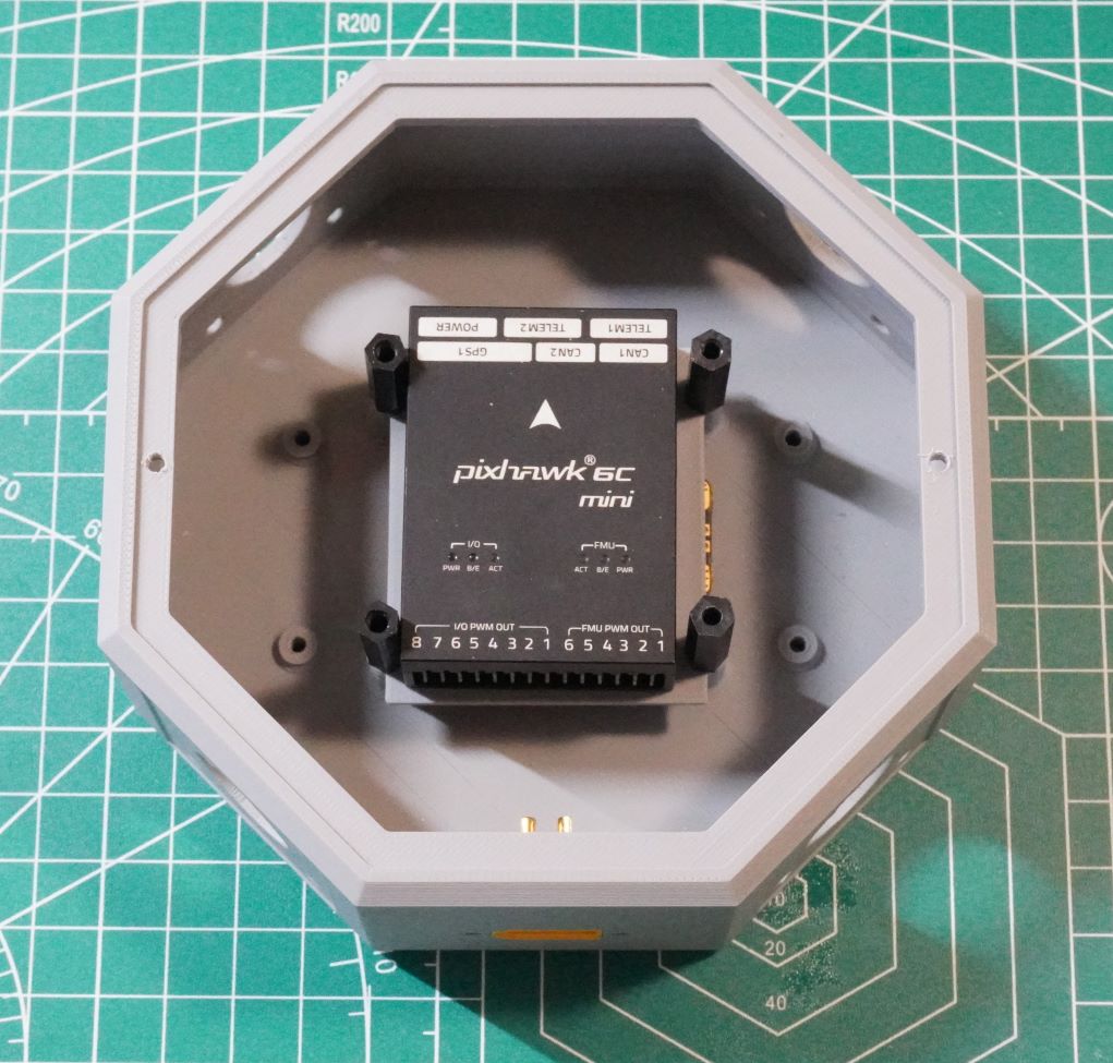
It is possible to secure the Flight Controller Tray with stand-offs to allow mounting an equipment tray above it.
Here the Large Equipment tray is mounted above the flight controller.
The Large Equipment Trays can be secured with stand-offs to add a second Equipment Tray.
Here the Small Equipment Tay is mounted on standoffs above the Large Equipment Tray.
The equipment trays can be used for mounting electronics. Here a M10 GPS and a Remote ID unit are mounted on the top tray. The lower tray has an ELRS receiver and a Blue Tooth radio module mounted.
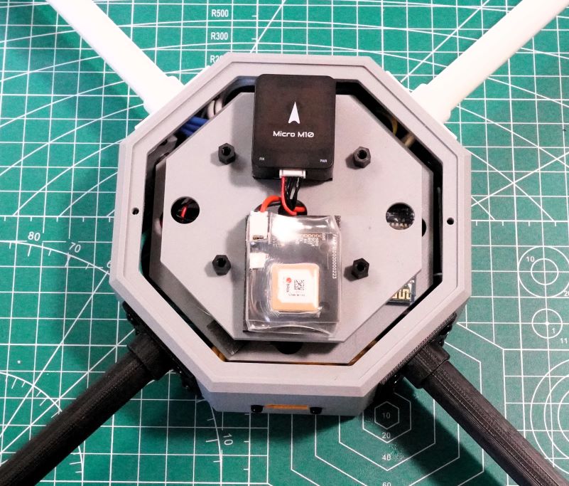
With both equipment trays, the electronics can still fit under the dome.