This article describes simple and inexpensive methods of integrating Sony cameras with Cube/Pixhawk flight controllers running Ardupilot. I’ve not tested these methods with Cube/Pixhawk flight controllers running PX4. I’d appreciate comments about these techniques from anyone in the PX4 community.
The methods described here are focused on simple photo mapping applications. The Sony Multi-Port USB connection provides for integration of many camera features and functions that are beyond the scope of this article.
In 2017 Micro Aerial Projects published an article on this topic. It was included in the ArduPilot wiki here:
https://ardupilot.org/plane/docs/common-pixhawk-camera-trigger-setup.html
This article expands the 2017 article by addressing five areas:
- Description of the Sony Multi-Port USB connection
- Cable fabrication for shutter triggering
- Ardupilot parameters
- Hot-Shoe signaling
- External camera power
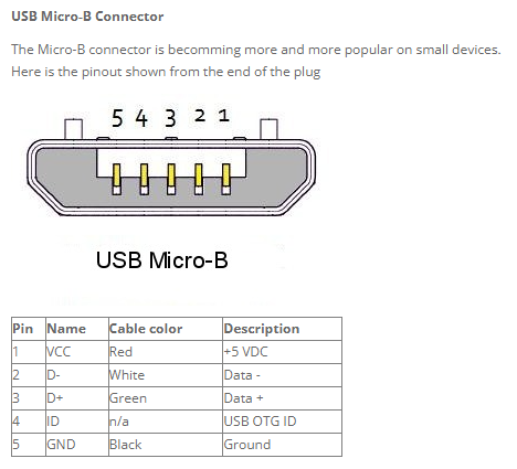
The Sony Multi-Port USB connector is an enhanced version of the USB Micro-B connector with 15 contacts. This standard micro-B USB connector has 5 contacts.
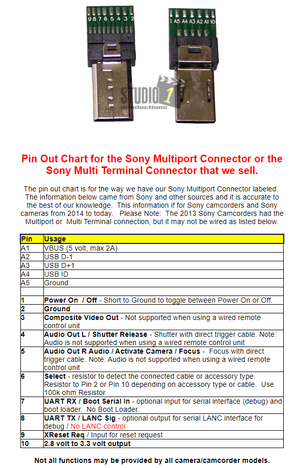
The Sony Multi-Port connector has 15 pins:
Blank Multi-Port USB connectors are available from various retailers such as this: https://www.aliexpress.us/item/2251832279066060.html
Advanced camera control devices such as the AirPixel Air Commander Entire can be integrated with Ardupilot for control over a wide range of camera functions such as exposure settings. Less advanced camera control devices such as the Seagull #REC2 can a limited range of functions such as zoom. The AirPixel Entire does not provide external camera power through it’s Multi-Port connection but the Seagull #REC2 does – if the camera model accepts USB Power Supply.
Cable Fabrication for Shutter Triggering
To use the Sony Multi-Port connector to trigger the camera shutter, Pin-2 (ground) and Pin-4 (shutter release) need to be momentarily connected. Just one or two tenths of a second is sufficient.
On Sony cameras equipped and configured for auto-focus, focus must be activated before the shutter will be triggered. This can be accomplished by connecting the Multi-Port Pin-5 (focus) to Pin-2 (ground). Focus and shutter release can occur simultaneously. Connecting Pin-5 and Pin-4 together ensures that auto-focus is triggered if required for shutter release.
ArduPilot controls the Cube/Pixhawk GPIO relays. The relay capability works well for making the connections to the Multi-Port pins for focus and shutter release.
Early versions of ArduPilot only allowed AUX ports to have GPIO relay capability. Now both AUX and Main ports support GPIO relays.
Occasionally pre-fabricated cables are offered for sale that connect the Sony Multi-Port with Cube/Pixhawk AUX or Main ports. The following are two examples of DIY cable fabrication.
Using a blank Sony Multi-Port USB connector, solder wires to pins 2, 4 and 5.
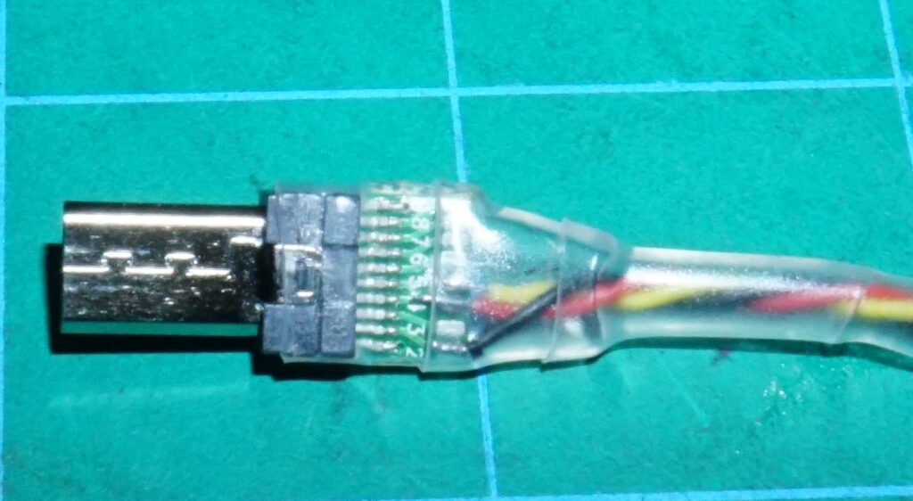
To protect the connector’s pins, I applied clear shrink wrap.
At the other end of the cable, combine the pin 4 and 5 wires to the pin on one side of a servo connector, and the pin 2 wire to the pin on the opposite side servo connector.
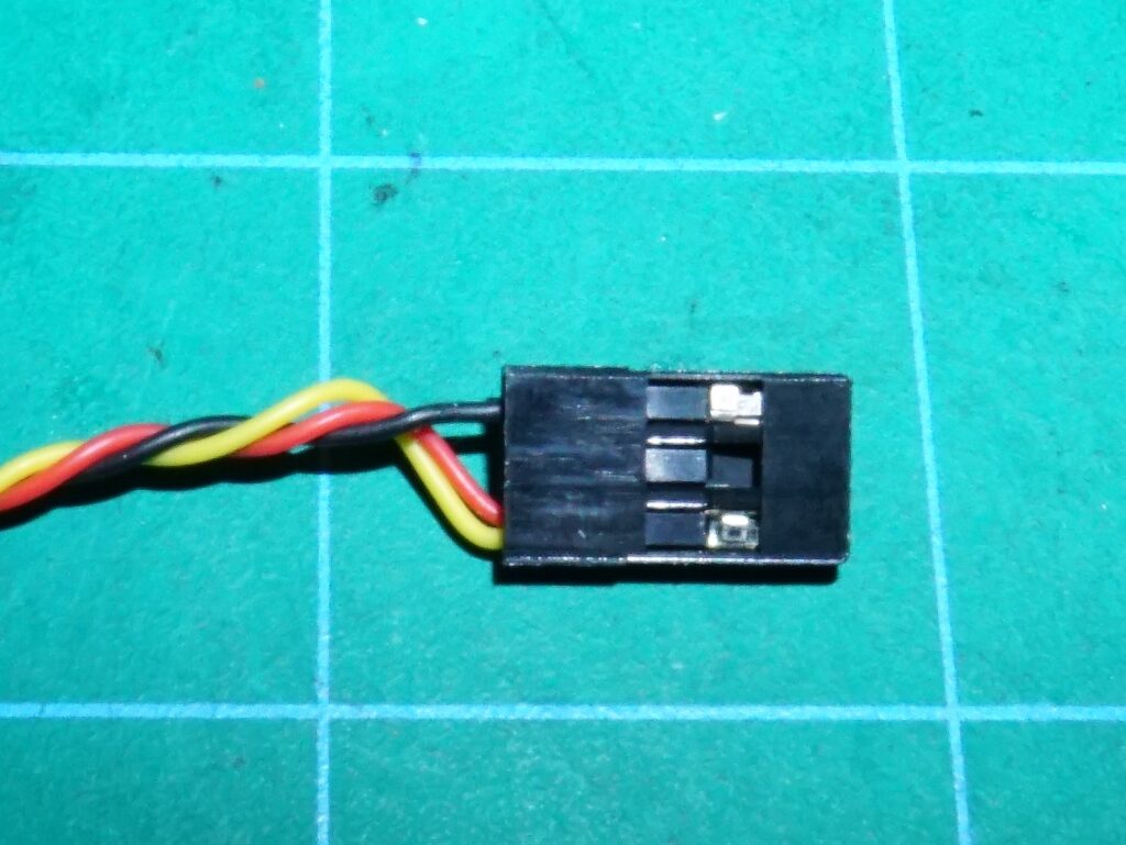
This fabrication method allows creating a cable of any suitable length. I’m using AWG-30 gauge wire in this example – but any gauge small enough to solder to the multi-port connector may be used. Only a miniscule current flows (and for a fraction of a second) when the GPIO/relay completes this circuit – so a very small gauge wire can be used.
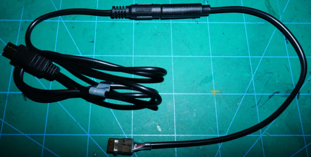
To reduce the effort in fabricating this cable, a manual shutter release device can be used. This remote shutter release device for Sony cameras with Multi-Port USB connections was available for less than $15.
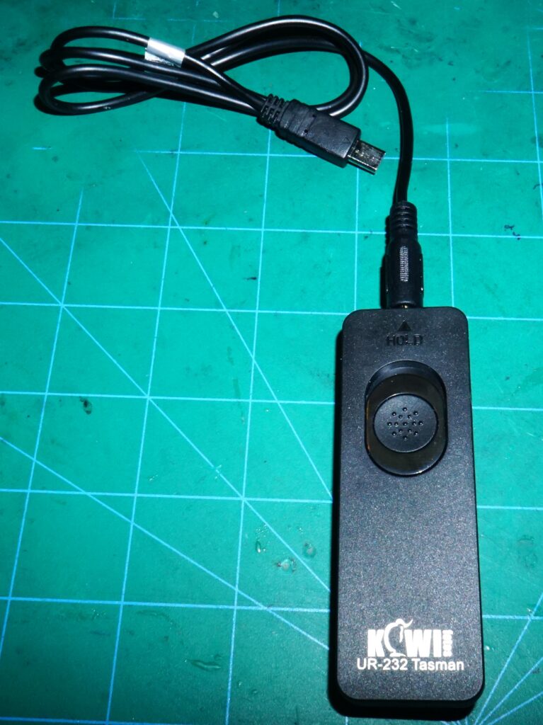
The cable on this device has a Sony Multi-Port connector with pins 2, 4 and 5 connected to a 2.5mm plug at the other end.
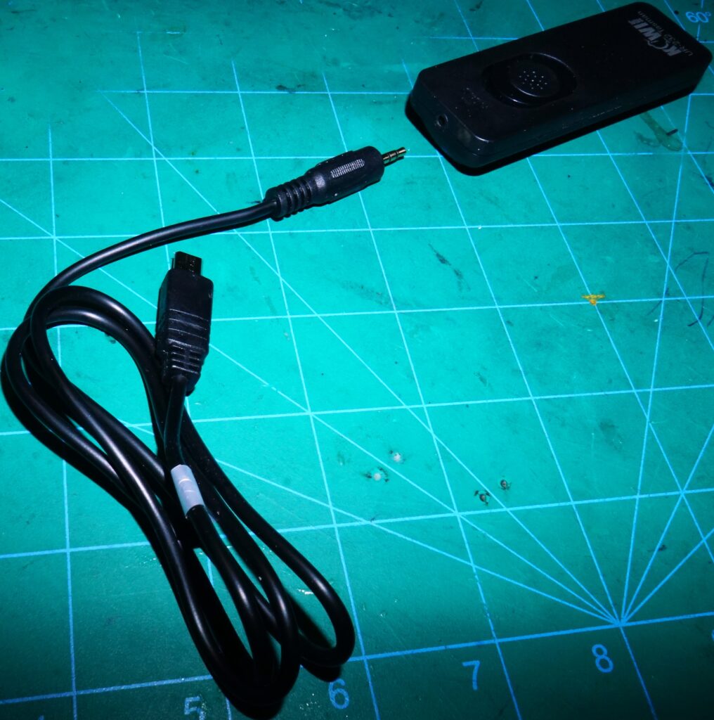
For less than $5 a 2.5mm jack with bare leads can be purchased. The bare leads can accept the servo connector as in the previous cable example.
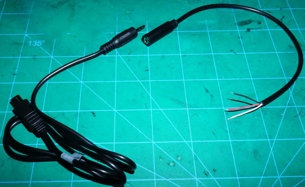
Determine which color wire was on the Multi-Port pins 2, 4 and 5 by simple testing. For example, by attaching the cable to the camera’s Multi-Port, the camera may focus by simply touching the white wire to the black wire. By then connecting the red wire – the shutter release may be triggered. This identifies the black wire as Pin-2 (ground), the white wire as Pin-5 (focus) and the red wire as Pin-4 (shutter).
Putting the red and white wires together on one side of a servo connector and the black wire on the opposite side of the servo connector was all that was needed to make this cable.
Ardupilot Parameters
Some Ardupilot parameters for triggering a camera shutter using the GPIO/relay capability have changed from earlier releases. There are more changes in the works. For example, a version currently in development has new parameters defined for multiple cameras. In configuring your Ardupilot parameters, it’s important to check the Ardupilot Complete Parameter List for any parameters you’re using for specific functions – for the version of Ardupilot you are using.
The parameters referenced in this article are based on the latest stable version of Ardupilot 4.3.
For Ardupilot to trigger the camera shutter, some sort of event has to occur that creates a MavLink message for camera shutter. There are three events that can create the MavLink camera shutter event.
- An RC Channel is associated with the camera shutter event.
- A ground control unit transmits a camera shutter event to the vehicle.
- An auto mission has statements causing the camera shutter event.
The RC Channel association with the camera shutter even requires setting an Ardupilot parameter. Originally, RC Channel-7 was required for the camera trigger. This requirement no longer exists – any available RC channel can be used.
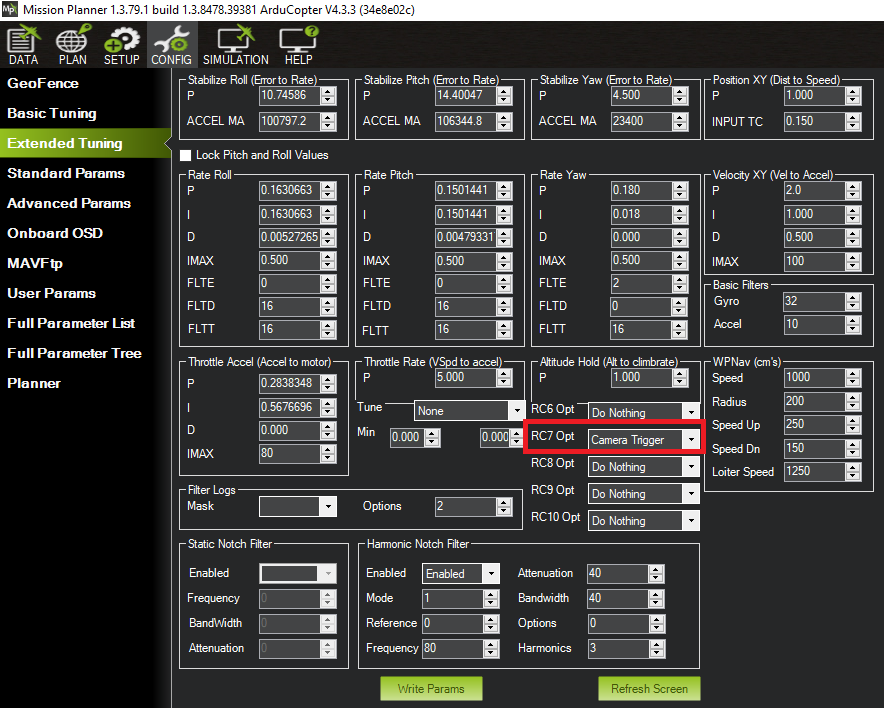
To configure an RC channel for the camera shutter, use the RC(n)_OPTION parameter and set it to “9”. (“n” is the channel number)
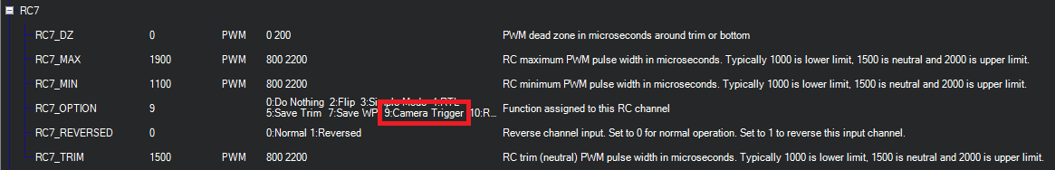
This can also be set on the Extended Tuning page.
Parameters are set for the actions Adrupilot will take for the MavLink camera shutter event. In this example, want ArduPilot to operate a GPIO/relay when the MavLink camera shutter event occurs. And we want the GPIO/relay to operate a certain way.
There are five parameters to set to use a GPIO/relay for a camera shutter trigger
- CAM_TRIG_TYPE=1 Ardupilot uses this parameter setting to know that a GPIO/relay is used for the camera shutter relay.
- CAM_RELAY_ON=0 Ardupilot uses this parameter to know how to set the GPIO/relay for the shutter trigger. “0” is for GPIO “low” – which is what the Sony MultiPort needs to trigger the shutter.
- RELAY_PIN=nnn Set “nnn” to the number representing the AUX or Main port connected to your camera shutter. For example, if you’re using Main-7 for your camera shutter cable, set this to “107”.
- SERVO(n)_FUNCTION=-1 This parameter tells Ardupilot that the “(n)” output port is a GPIO/relay function. For example if Main-7 is used for the GPIO/relay for camera shutter, you would set SERVO7_FUNCTION=-1
- CAM_DURATION=n The GPIO/relay has to be activated long enough for the camera to focus before the shutter is released. This parameter sets this time – in tenths of seconds. The Sony cameras I’ve tested all focus fast enough that I can set this parameter to 3. Setting it to 5 (5/10 or half a second) would be more conservative.
Hot-Shoe Signaling
ArduPilot has two ways to create geotags for photos. The first way is to use the time the MavLink camera shutter event occurred. In other words, the geotag is where the vehicle was when the camera shutter was commanded to trigger.
The other way is to create a geotag on the precise time the camera shutter was released. On a moving vehicle, the distance between where the vehicle was when the shutter was commanded and when it the shutter was actually released could be several meters.
The geotags are created from messages in the ArduPilot dataflash log. (The BIN file.) If no hot-shoe signal is used, Ardupilot stores a “CAM” message with the geotag data. The geotag data in this case is recorded when the camera shutter was commanded.
If a hot-shoe is configured and used, two geotag messages are recorded in the log. A “CAM” message is stored with the geotag data from when the camera shutter was released. A “TRIGG” message is recorded when the camera shutter was commanded.
If there’s a failure in the hot-shoe signal, then the “CAM” messages won’t be created. The “TRIGG” message however are still recorded with their geotag data. While these messages have less accurate geotags, they do provide a fall back.
To use Hot-Shoe input two things are required:
- A device that connects the camera’s Hot-Shoe source to an AUX port on the Cube/Pixhawk.
- ArduPilot parameter settings to configure for using the Hot-Shoe signals for geotags.
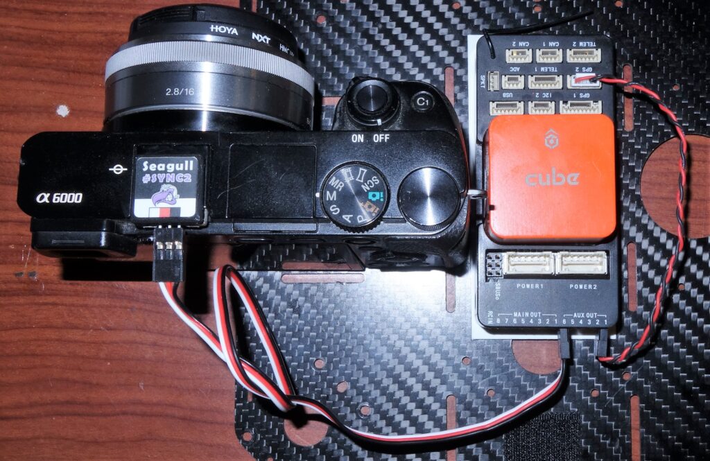
I use a Seagull #SYNC2 device attached to my camera’s hot-shoe for sensing the Hot-Shoe signal. It connects with a standard 3 wire servo-style cable to an Aux port. (Only Aux ports, not Main ports, can receive input signals.)
The #SYNC2 requires 3 to 5 volts on the servo rail for power. I don’t have a BEC in this range on my vehicle, so I bring the 5V from the GPS-2 port to the servo rail to power the #SYNC2.
Five parameters must be set to process the Hot-Shoe input signal:
- CAM_FEEDBACK_PIN=nn This parameter tells Ardupilot which Aux port is used for the hot-shoe signal. For example Aux-6 is indicated by “55”.
- CAM_FEEDBACK_POL=n Ardupilot uses this parameter to know if the hot-shoe signal is “high” or “low” when the shutter is triggered. This information has to come from the manufacturer of the hot-shoe adapter. For the Seagull #SYNC2, the hot-shoe signal is low – so the value of “n” is “0” as defined on the Ardupilot parameter list.
- SERVO(n)_FUNCTION=-1 Just as in in defining the configuration of the Aux or Main port for the camera shutter relay, Ardupilot needs to know that the port for hot-shoe input is to be configured as a GPIO port. Main ports 1-8 are Servo1-Servo8. Aux ports 1-6 are Servo9-Servo14. To use Aux Port-6, set SERVO14_FUCTION=-1
External Camera Power
Some Sony cameras with the Multi-Port USB connector can receive external power through this connector. To know if a camera model supports this, you can look up in the camera’s manual for a section called “USB Power Supply.” If this section exists, this feature is available.
As an example, the Sony a6000 does not have this feature. But according to it’s manual, the Sony a6100 does have it. My Sony RX0ii and RX100ii also support USB Power Supply.
Some camera control devices such as the Seagull #REC-2 have the ability to provide external camera power through the Sony Multi-Port. Some camera control devices such as the AirPixel Air Commander Entire do not have this feature.
It may be possible to add USB Power to a custom fabricated Multi-Port cable. For example, it may work by applying 5V to the Multi-Port pin A1 and ground to pin A5. If this works, it would still only work on cameras that support the USB Power Supply function.
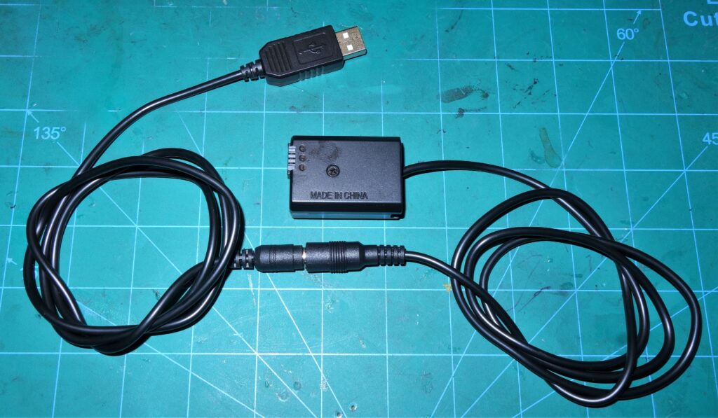
Sony and after-market manufactures make what Sony calls a “DC Coupler” that provides external camera power using a dummy battery and a power source such as a USB connection.
Cameras where Sony make a DC Coupler have a small opening in the battery door allowing the battery door to close with the dummy battery in place.
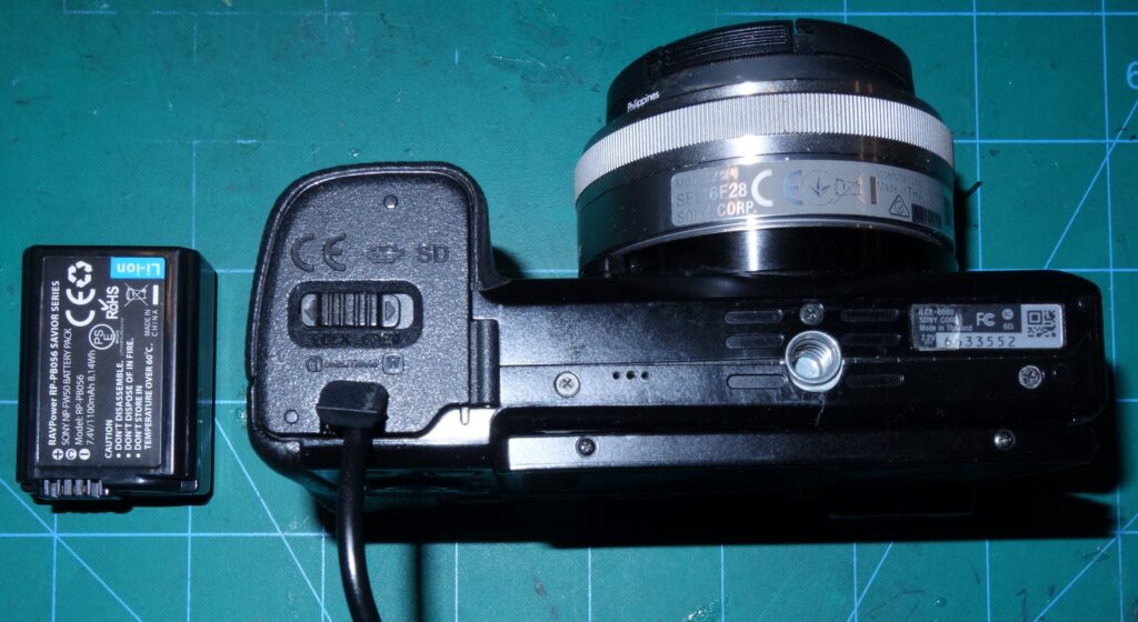
It’s important to be careful about understanding what voltage a DC Coupler provides to the Camera. The DC Coupler’s voltage should match and not exceed the voltage of the battery for the camera. If the dummy battery presents to high a voltage to the camera, it will likely cause the camera to fail. If the voltage is too low, the camera may not operate correctly.
Here’s an example of a DC coupler that gets power from a USB connection. What you can’t tell without test however is what voltage is delivered to the dummy battery. Measuring the voltage at the barrel connector the USB power is regulated up to to 8.14 volts.
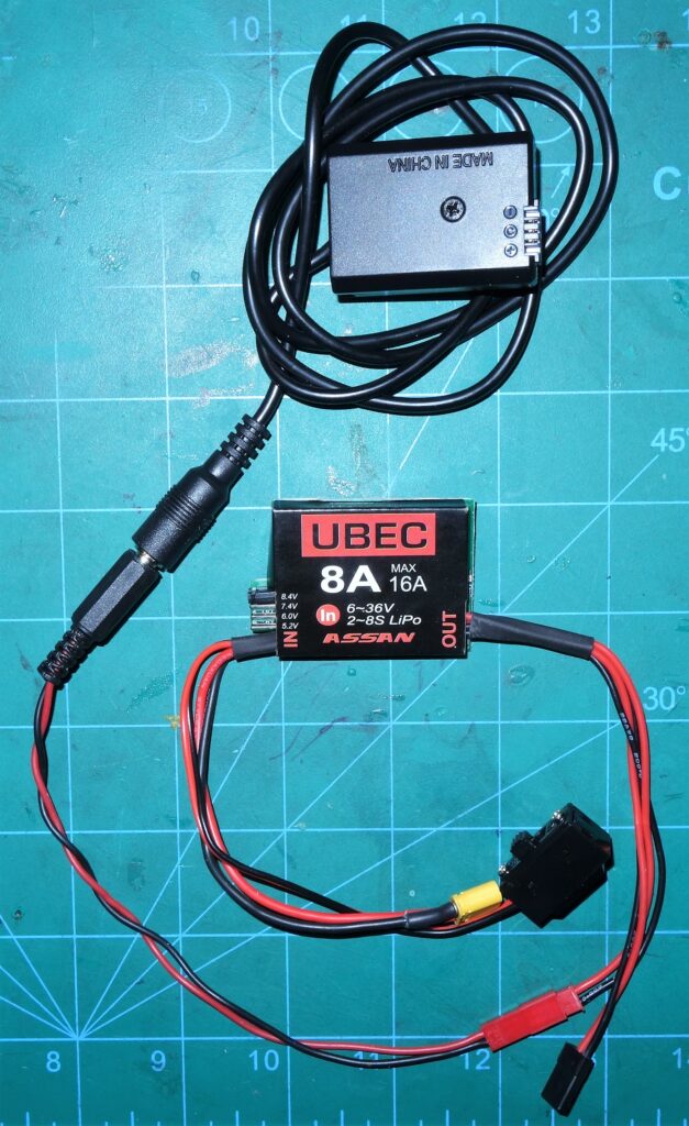
I decided to power the Camera on my vehicle I’d use an 8.4V BEC. This is slightly higher than the voltage of my DC Coupler’s USB output – but 8.4V matches the voltage of a fully charged 2S Li-Ion battery pack – which is what the camera uses.
Video Example
The video below shows a Sony a6000 with the shutter operated by the GPIO/relay of an Orange Cube running ArduPilot.
Precise geotags are created using hot-shoe input using a Seagull #SYNC2 hot-shoe adapter.
The Sony a6000 is powered using a DC Coupler dummy battery and an 8.4V BEC.
Comments
Please leave comments – especially if you find errors or omissions. I’ll make the necessary corrections as soon as possible. Thank you.