Revisions
- Revision 1 – 3/26/2023 – The language on saving camera settings has been improved. A section on setting the SERVO(N)_FUNCTION parameters has been added.
The Foxtech Map-02 camera is a lightweight camera designed for sUAS applications. The Map-02 uses the Sony a5100 internals in a lightweight plastic box shell. The Map-02 camera is similar to the Map-01 camera – both use Sony a5100 internals. Their manuals are similar but I’ve not tested the Map-01.
Because some of the a5100 components have been deleted in the Map-02, the connections to the camera and some of the camera’s operations have special requirements.
I’ve mounted my Map-02 on a quad-copter and used it for photo mapping missions. The Map-02 has some functions I’ve not explored – such as video capture. This article will cover only those features and functions I’ve used.
- References
The Foxtech Map-02 user manual is here: https://www.foxtechfpv.com/product/cameras/map02/Map02-manual-180927.pdf
The ArduPilot parameter wiki is here: https://ardupilot.org/copter/docs/parameters.html
- Power
The manual for the Map-02 has strong warnings about not exceeding 8.4V for powering the camera. No minimum voltage is given.
The manual also cautions against “hot-plugging.” I’ve not been able to find what “hot-plugging” means.
I first tried a 7.2V UBEC. The camera would take pictures with this power supply, but it would not format the SD card. Attempting to format the SD card with a 7.2V power supply it would fail with an error statement to the effect that the battery was too low for that operation.
With 7.2V power, the camera screen displays a battery icon that is discharged. With 8.4V power, the battery icon is displayed as charged.
I found only a few UBECs that deliver 8.4V. I believe many are designed for R/C cars. The one I selected is made by Assan. It works well powering the Map-02. Another brand of UBEC that can support 8.4V is Castle Creations.
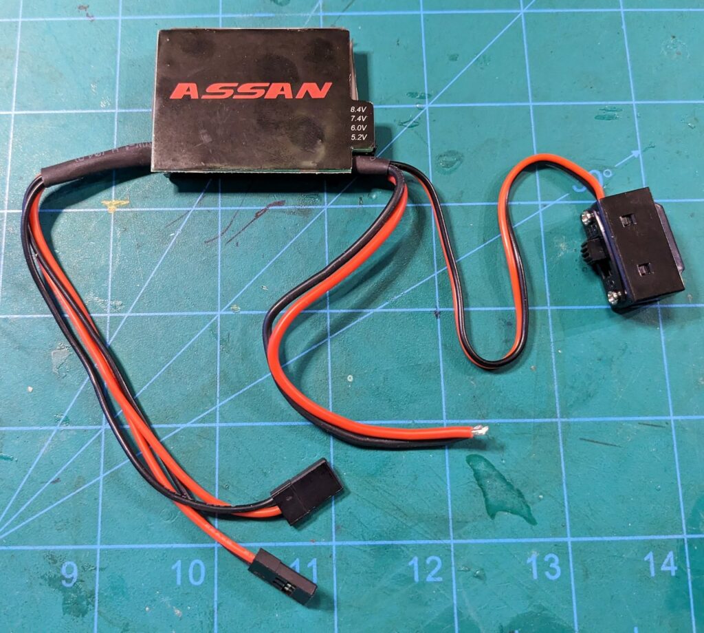
Output voltage on this Assan UBEC can be selected with a jumper. Two output leads are provided, along with an ON/OFF switch. This UBEC’s switch turns out to be handy – it makes it easy to turn off the camera when necessary.
- Camera Switch
The Map-02 has a small camera switch built into it’s wiring harness. This switch will deactivate the camera – but that’s not it’s primary function. Using the camera switch to deactivate the camera causes the camera to save any camera settings that have changed. For this to work – the camera still has to be receiving power from its normal power source.
The switch is very small and may be too fragile for regular use to de-energize the camera. I suspect its use should be limited only to saving camera settings.
The procedure for saving camera settings:
- Power the camera normally.
- Change the camera settings.
- Use the camera switch to deactivate the camera and save the new settings.
- Use the camera switch to reactivate the camera – and check that the new settings were saved.
- De-energize the camera by turning off the camera’s main power source.
Once these steps are completed, you can turn the camera switch back to ON. Then when the camera is re-energized from it’s main power source, it will operate with the new settings.
I have noticed that when a lens is installed with a variable aperture, turning off the camera switch, it causes the aperture to close. I don’t know if this is significant. In normal operation I power the camera on and off from the main power source – so a lens with a variable aperture does not close its aperture.
- SERVO(N)_FUCTION GPIO settings
Both the camera shutter trigger and the hot-shoe require ports configured as GPIO. In the current release any Main or Aux port can be used as a GPIO relay to trigger the shutter. However only Aux ports can process GPIO input signals – such as the hot-shoe.
There have been changes to these GPIO capabilities and configuration settings a few revisions ago. These instructions work for the current stable version of ArduCopter.
To set a port as a GPIO, use the SERVO(n)_FUNCTION parameter and set it to “-1”. For example, I use the Main-8 port as the GPIO relay to trigger the shutter. And I use AUX-7 as the hot-shoe input connection. So I make set these parameters:
SERVO7_FUNCTION=-1
SERVO13_FUCTION=-1
- Camera Shutter Trigger
There are two leads on the Map-02 wiring harness identified with labels and colors as the leads for the camera shutter trigger. The Map-02 manual also identifies these leads by color and position on the harness connector. The camera shutter trigger wires are yellow and green.
The camera’s shutter can be triggered when these two wires are connected. This can be easily tested by simply shorting these two wires together and listening for the camera shutter to click.
ArduPilot can command the camera shutter trigger using a flight controller GPIO relay. Any of the carrier board’s Main or Aux ports can be configured by ArduPilot to be a GPIO relay for the camera shutter trigger.
To configure ArduPilot to use a GPIO relay for the camera shutter trigger, you must set the parameter CAM_TRIG_TYPE. The value for GPIO relay is “1”.
CAM_TRIGG_TYPE=1
The specific Aux or Main port used as the camera GPIO relay is determined by the ArduPilot parameter RELAY_PIN. The ArduPilot parameter wiki lists all the available values. I use the Main-8 port, which is a value of “108.” So I set the parameter:
RELAY_PIN=108
The camera shutter trigger wires have polarity – so it’s important to identify them properly when connecting them to a carrier board GPIO relay using an Aux or Main port. The green wire should be connected to the pin on the Aux or Main port labeled as “–” or ground. The yellow wire should be connected to the pin on the Aux or Main port labeled as “S” or the signal pin.
As a relay, the GPIO can switch between states of “HIGH” and “LOW.” The Map-02 manual states the GPIO relay most be in state “LOW” to trigger the camera shutter. This is set using the ArduPilot parameter CAM_RELAY_ON set to the value of “0” – for “LOW”.
CAM_RELAY_ON=0
For this to work, the default GPIO relay condition must be “HIGH”. (or “ON” as stated in the ArduPilot parameter documentation.) This is set with the ArduPilot parameter RELAY_DEFAULT. The parameter value for “HIGH” is “1”.
RELAY_DEFAULT=1
Its necessary to set one more shutter trigger parameter. This parameter sets the length of time the GPIO relay stays at “LOW” to trigger the shutter properly: CAM_DURATION. This parameter’s value is in tenths of seconds. Through experimentation, I found the shutter will trigger with this set to as low as one tenth of a second. However, if auto-focus is used, a longer time is required. I find three tenths worked for my lens. So I set this ArduPilot parameter:
CAM_DURATION=3
There are several other ArduPilot parameters that control the function of GPIO relay for a camera shutter, and I’ve left them all at their defaults. For your implementation you may wish to review them under the CAM_xxxx parameters.
- Hot Shoe
A camera’s hot-shoe signal is used to precisely geo-tag images. The hot-shoe signal occurs at the precise time the camera shutter is triggered. It is still possible to geotag images without using a camera’s hot-shoe signal – but without it, only the time the camera shutter was commanded to trigger is available for the geotag. As the camera may be moving, this causes a delay, and the geotag will not be accurate.
The Sony a5100 camera does not have a hot-shoe. Foxtech has modified the Sony a5100 internals in the Map-02 to provide a hot-shoe signal.
Geotagging devices such as the Emlid Reach M2 use a hot-shoe signal, combines it with GNSS Receiver position data – and produces a geotag for each time an image is captured. I’ve used a more simple approach – I connect the hot-shoe signal to a flight controller Aux port, and use the ArduPilot dataflash logs to create the image geotags using a Mission Planner geotag utility.
Both Aux and Main ports on ArduPilot flight controller carrier boards can serve as GPIO relays. Only Aux ports can accept input signals. So to connect a camera’s hot-shoe signal to the carrier board, an Aux port must be used. The Map-02 hot-shoe lead is white and labeled “PPK.” I connect it to the signal pin (“S“) of the Aux port I’m using for hot-shoe input.
The Aux port for the hot-shoe signal is identified by the ArduPilot parameter CAM_FEEDBACK_PIN. I use Aux port 6 – and the value for that is 55 – which is the pin number on the carrier board. For my copter I set the ArduPilot parameter:
CAM_FEEDBACK_PIN=55
An ArduPilot parameter must be set to the appropriate hot-shoe trigger signal polarity with the parameter CAM_FEEDBACK_POL. The hot-shoe trigger signal is either HIGH or LOW. The Foxtech Map-02 manual does not contain any information about the hot-shoe signal. I elected to use LOW – and the value for CAM_FEEDBACK_POL for trigger low is “0”. For my copter I set the ArduPilot parameter:
CAM_FEEDBACK_POL=0
- Hot-shoe Signal Compatibility
After connecting the Map-02 hot-shoe lead to the carrier board Aux port, ArduPilot generated errors. The messages were “ISR Flood.” I learned that this error indicated that ArduPilot detected an improper signal on the hot-shoe input and deactivated the GPIO pin used by the hot-shoe to prevent a possible firmware crash.
Seeking help, I asked the ArduPilot community on discuss.ardupilot.org. The consensus was that the hot-shoe signal from the Map-02 was “floating” and that either a “pull-up” or “pull-down” resistor was required.
One contributor provided a diagram from old ArduPilot documentation that illustrates the pull-up resistor solution.
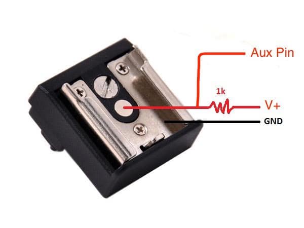
I fabricated and implemented a 1K ohm pull up resistor like this:
This solution worked initially – but then failed the following day. I’ve been unable to determine why it failed. My best guess is that it was because the voltage was too high. I used the same 8.4V UBEC as the V+ source because it was convenient.
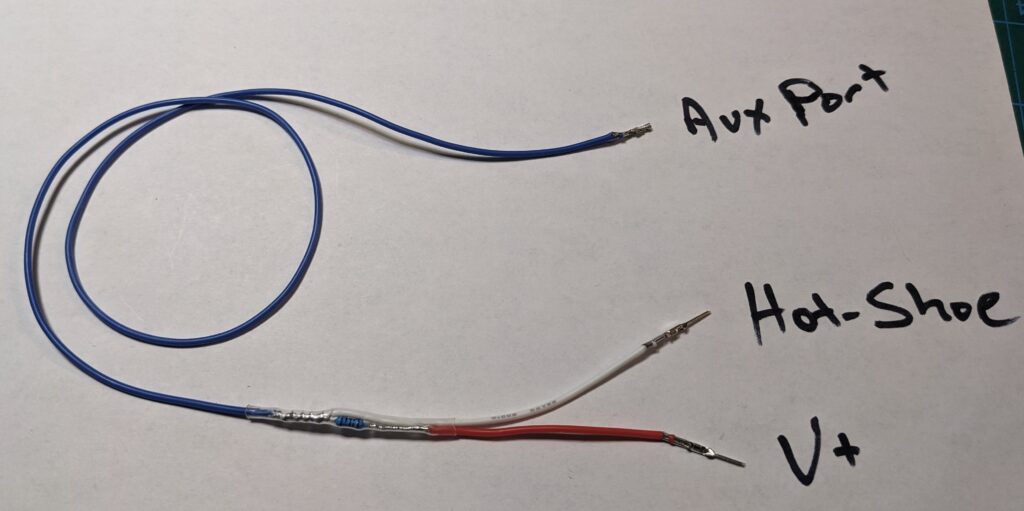
Through experimentation and diagnostic work, I found a different solution that worked. I simply added a 2K ohm resistor in series between the hot-shoe lead and the Aux port signal pin.
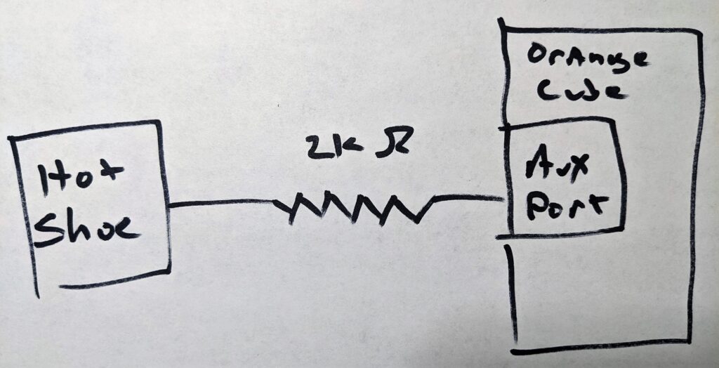
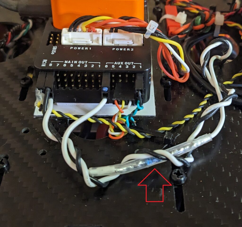
This solution has worked reliably for mapping missions that capture well over 1,000 images.
- Camera Power Up Procedure
One quirk of the Map-02 camera is that it’s unable to retain time and date settings. This means that every time the camera is powered up, it begins at a screen that allows entering the time and date settings screens – or continuing on without making these changes.
These screens are followed by another informational display showing the website address for the Sony camera’s app.
The Map-02 manual says that the camera’s shutter must be operated two times within the first 10 seconds of powering up the camera – or the camera will crash. In my experience, this is more or less true. But typically more than 10 seconds is allowed.
To prevent this crash, I use the following procedure:
- With the Assan UBEC switched off, I power up the copter normally and connect it to my ground control station.
- After establishing connection between the drone and the ground control station, I switch on the Assan UBEC to power up the camera.
- It takes about 7 seconds for the camera to power up. If the camera has a video monitor connected, or video display on the ground control station, the initial camera display screen will appear. If no video display is available, waiting 10 seconds is sufficient.
- Using the ground control station, activate the camera shutter trigger once. You will not hear the camera shutter click. But if a video display is available, you’ll see that the camera now presents the normal display for taking pictures. You should allow the camera to remain on this screen for three or four seconds, and then immediately follow the next step.
- Using the ground control station, activate the camera shutter trigger several more times. I usually trigger the shutter four times – and I listen to be sure I hear the shutter click each time. This will capture an image for each trigger activation, and record the events in the ArduPilot logs. So when using the Mission Planner geotag utility, these initial images are included. They can be removed once they are processed by the geotag utility.
- Auto-focus on Camera Startup
On my installation, the camera is permanently mounted in a fixed position facing down. So when starting up the drone, the camera lens is only a few inches from the ground. This creates a problem if the camera is using auto-focus. The ground is too close to the lens for the auto-focus to work, so the required shutter triggers at startup won’t work.
There are two solutions: 1) Pick up the drone and face it away from the ground on the initial camera triggers. 2) Do not use auto-focus. Use manual focus instead.
- Comments and Corrections
So far in my usage of the Map-02 camera, it works well for the photo mapping missions I had intended. It is very light weight – especially using one of the very lightweight E-Mount lenses available. And it consumes very low power.
It took a bit of time to sort through the installation and integration on my drone. I hope by writing down these experiences here, others can more easily take advantage of this camera.
Please use the comments section below to make comments – and especially make corrections in case I’ve gotten something wrong.
Hot plugging means plugging in while power is on. Turn off power then plug in and turn on power.
Thank you – I appreciate your helpful comment. May I please ask you to be a bit more specific? Are you referring to the little camera switch on the harness? Does that have to be off before applying power to the camera? That’s typically how I do it – but I used to just leave the little camera switch on the harness on all the time except when I changed camera settings. That worked OK – but these days I turn the camera harness switch on only after there’s power available to the camera, and I turn the camera harness switch off before removing power from the camera.
The Foxtech warning is pretty strong – I’d really hate to damage the camera by powering it up and down incorrectly.
Since my UBEC has a switch, it’s easy to control on my copter.
I don’t think the camera switch on the harness has a great number of duty cycles – so I’d prefer to not operate that switch any more than I have to.
in your ArduPilot Integration with Sony Multi-Port USB Equipped Cameras technical write-out, you used Seagull #SYNC2 to connect from the camera to the Aux6 port.
For this example, do you just connect from the white cable (4) of the Foxtech power switch cable and series with the 2Kohm resister and then directly connect to the Aux6 port for the hot-shoe signal? Foxtech example is connected to the Reach M+.
https://www.coptercam.tech/technical-article-ardupilot-integration-with-sony-multi-port-usb-equipped-cameras/
https://www.foxtechfpv.com/foxtech-map-02-camera.html
The Sony a6000 and FoxTech Map-02 have different ways of supporting the Hot Shoe function.
The FoxTech Map-02 uses the Sony a5100 internals. This camera does not come with a Hot Shoe – so FoxTech added this capability to the Map-02. As noted in my article about the FoxTech Map-02, the wire provided for this purpose requires a 2K Ohm resistor to function properly when connected to an Aux Port. This resistor is in series with the FoxTech Hot Shoe wire – I believe it’s labeled PPK.
The FoxTech example of connecting to the Reach M+ is similar to my example – but the Reach M+ is electrically different from the Aux port. It may not require a resistor.
The Sony a6000 comes with a Hot Shoe on the camera. So with this camera it’s possible to use the Seagull #Sync2 device to connect the Hot Shoe to the Aux port. No extra resistor is required.
I hope this answers your question.