I recently installed a FoxTech Map-02 camera to a quad-copter for photo survey missions and photogrammetry. My copter uses ArduPilot, a CubePilot Orange Cube and an ADSB Carrier Board. This camera has two leads that control the shutter. When the two leads are connected together the shutter is triggered. This requires using the ArduPilot relay function to actuate the camera’s shutter.
Several revisions to the ArduPilot copter firmware have been released since the last time I used an ArduPilot relay to control a camera shutter. Some of the recent revisions have changed how ArduPilot relays are configured. I decided to do the FoxTech Map-02 installation from scratch to be sure I’ve done things correctly with the current ArduPilot copter release (4.3.1).
The ArduPilot relay functionality works well – but I found it required a bit of an effort to sort through the various ArduPilot wiki posts to get it configured properly. There is more than one way to approach a camera trigger using ArduPilot relays. I had to find the best method for my copter. This article describes my particular configuration. I hope this article may be useful to others need to implement a AdruPilot relay for camera shutter control.
There are three helpful concepts for controlling a camera shutter with ArduPilot:
- “Trigger Camera Shutter” is the event defined in the ArduPilot firmware to cause a camera shutter to be triggered. When this event occurs, ArduPilot issues a MavLink command to act upon the “Trigger Camera Shutter” event. There is more than one way to initiate this event and its associated MavLink command. And there is also more than one way for ArduPilot to act when this event occurs.
One way to cause the “Trigger Camera Shutter” event is to set ArduPilot parameters to associate an R/C transmitter channel PWM values to the “Trigger Camera Shutter” event. Traditionally, this is channel 7. There are ArduPilot parameters that allow setting the camera shutter channel and it’s PWM values to trigger the shutter. This allows for the pilot to manually flip a switch or button on the R/C transmitter to actuate the camera shutter.
A ground control program can also allow the pilot to manually actuate the camera shutter. By manually using the ground control program’s “camera shutter” button, a “Trigger Camera Shutter” MavLink command is sent to the copter over a telemetry radio. This ground control program can be a computer that is connected to the copter over a telemetry radio – or an app running on an intelligent controller such a a CubePilot HereLink. Mission Planner, Qgroundcontrol and Solex apps all have this capability.
“Trigger Camera Shutter” events can also occur automatically. Auto mission waypoint files can contain lines causing the “Trigger Camera Shutter” event to occur automatically based on criteria – such as distance flown.
Both the R/C channel method and the ground control program methods can exist and function simultaneously. One way of looking at it is that the ground control program’s ability to trigger the camera shutter supplements the R/C channel method. Either or both can be present and utilized.
There are even special cases such as commanding the copter to both aim the camera and take a picture by clicking on a ground control computer’s map. - There are two ways the “Trigger Camera Shutter” event can be executed for shutter triggering. One way is to set ArduPilot parameters so that a defined PWM value is presented on a servo channel when the camera shutter is to be triggered. This is typically how a camera shutter controller such as a Seagull or Airpixel device operates. Some cameras also accept PWM signals directly to control their shutters.
The other way is to set ArduPilot parameters to actuate the GPIO pin “relay” function. Either one method of execution or the other must be selected – both cannot be used simultaneously. - The ArduPilot relay as implemented on carrier boards using GPIO pins. Traditionally these pins are on the Aux ports – but the Main ports can also be used. As GPIO pins, they don’t operate exactly like a “relay” where contacts are either open or closed. Instead, GPIO pins configured as relays have two states: High and Low. In the Low state, the circuit between pins is open and no current can flow through it. In the High state, a very small current at the flight controller’s voltage (3.3V or 5V) is presented for a period of time. That period of time can be configured or controlled. My FoxTech Map-02 camera shutter requires only 0.1 second.
Traditionally, the voltage on the GPIO pins might be used to command a transistorized relay that requires very low current. Perhaps this is why ArduPilot calls this feature a “relay.”
In the case of my Foxtech Map-02 camera, no current or voltage is required – only that the circuit between the two shutter leads on the camera be closed. It turns out that the effect is the same – as long as the polarity is correct. The camera shutter leads are allowing a very small current of a low voltage from the camera to pass when the two leads are connected. When connected to the GPIO pins in the High state, the camera’s current flows with the GPIO’s current – as long as the polarity is correct for the same direction of current flow.
ArduPilot wiki articles:
There are several articles in the ArduPilot wiki with essential information about setting up a camera shutter using a relay. I suggest going through them in the following order.
This wiki describes the settings required to configure GPIO pins for your camera shutter relay. There have been changes to GPIO parameters in recent ArduPilot releases – and it’s now quite a bit simpler to make the right parameter settings.
This article covers a broad gamut of things pertaining to GPIOs – both in current and older ArduPilot revisions. But with the current ArduPilot release (4.3.1) there is only one parameter to set for configuring a GPIO pin for a camera shutter. You simply have to set SERVO(x)_FUNCTION=-1 where (x) is the Main or Aux port you’ll be using.
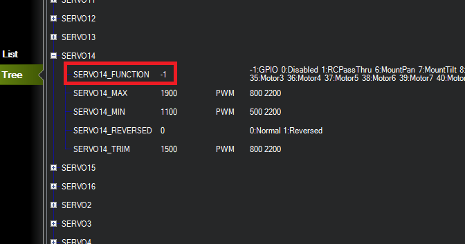
The SERVO(x) numbering starts with the first the Main servo port, and followed with the Aux servo ports. My carrier board has 8 Main ports and 6 Aux ports. I’m using the 6th Aux port – so it’s “servo 14”.
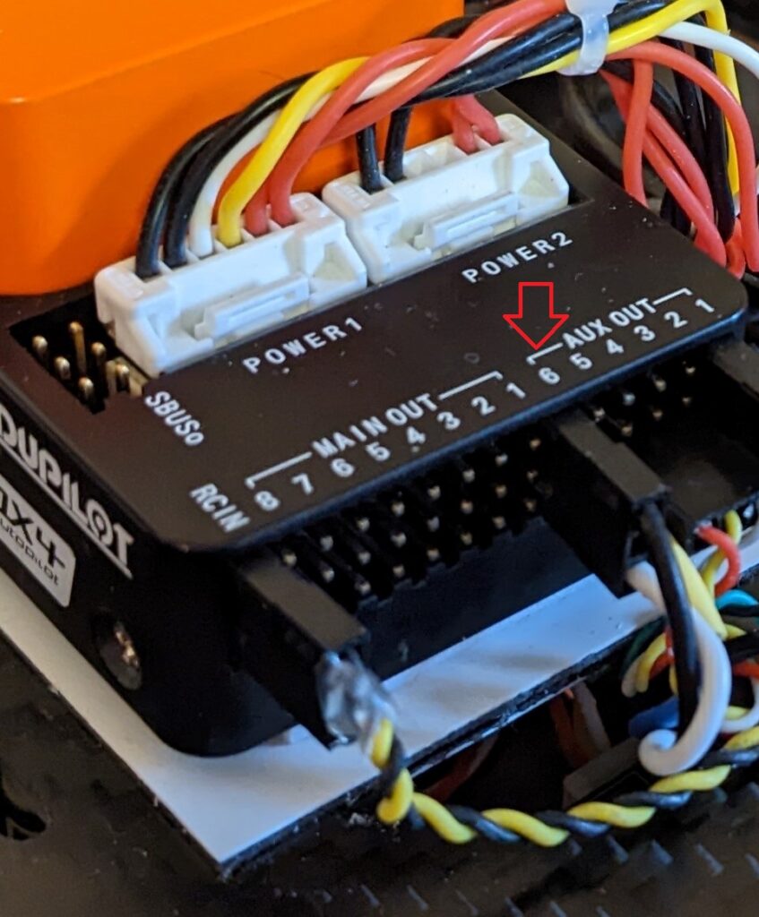
This photo shows the camera shutter leads connected to Aux port 6 – which is configured to function as a relay.
- Relay Switch – https://ardupilot.org/copter/docs/common-relay.html
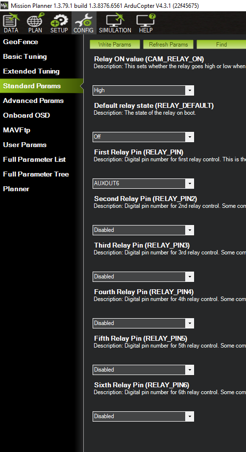
This wiki explains how several ArduPilot parameters control how a GPIO relay functions. It introduces a Mission Planner screen under Standard Parameters that show some of these parameters.
Using the CONFIG – Standard Parameter screen’s FIND button, when you search for “relay” you’re presented with the following screen. In my opinion this screen can be confusing.
For simplicity and clarity, I recommend using the CONFIG – Full Parameter Tree screen. First, navigate the tree to the RELAY parameters.
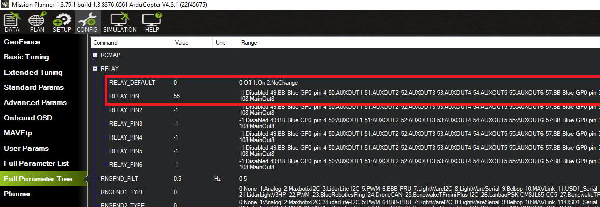
The RELAY_DEFAULT parameter sets the default state of relays. Instead of options for HIGH and LOW, it lists options for ON and OFF and NO CHANGE. From my testing it appears ON=HIGH and OFF=LOW.
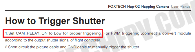
My camera’s (Foxtech Map-02) documentation states CAM_RELAY_ON=0 (low) for triggering. So I set RELAY_DEFAULT=1. This means the relay goes from HIGH to LOW when the shutter is triggered. The documentation for your camera may be different.
I want to use the Aux-6 port for the camera shutter, so I set RELAY_PIN=55 which is for the Aux-6 port.
The next thing to set is the way a “Trigger Camera Shutter” event operates the relay. Using the CONFIG – Full Parameter Tree screen, navigate to the CAM parameters.
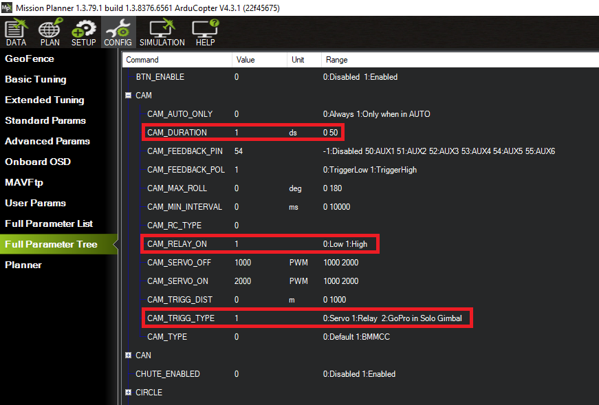
The primary parameter to set is CAM_TRIGG_TYPE=1. This configures the ArduPilot “Trigger Camera Shutter” event to operate a relay.
Some of the CAM_xxx parameter control the function of a relay used as a camera trigger, but some other parameters are for using PWM signals to control a camera shutter. All the CAM_xxx parameters for PWM signals can be ignored.
For my camera, next parameter to set is CAM_RELAY_ON=1. This will make the relay go HIGH when the “Trigger Camera Shutter” event occurs. My camera needs this condition on it’s shutter control leads to activate the shutter.
The last parameter required for my camera is CAM_DURATION=1. This sets the length of the time the relay is in the HIGH state when the “Trigger Camera Shutter” event occurs. This parameter is in deci-seconds – and through testing I found that the relay only has to be at the HIGH state for 0.1 second to activate my camera’s shutter. This allows the shutter to be triggered again subsequently at the shortest possible interval.
This wiki article also describes how relays can be used from other command sources. This is interesting – but it’s not necessary to review them for the purpose of camera shutter triggering.
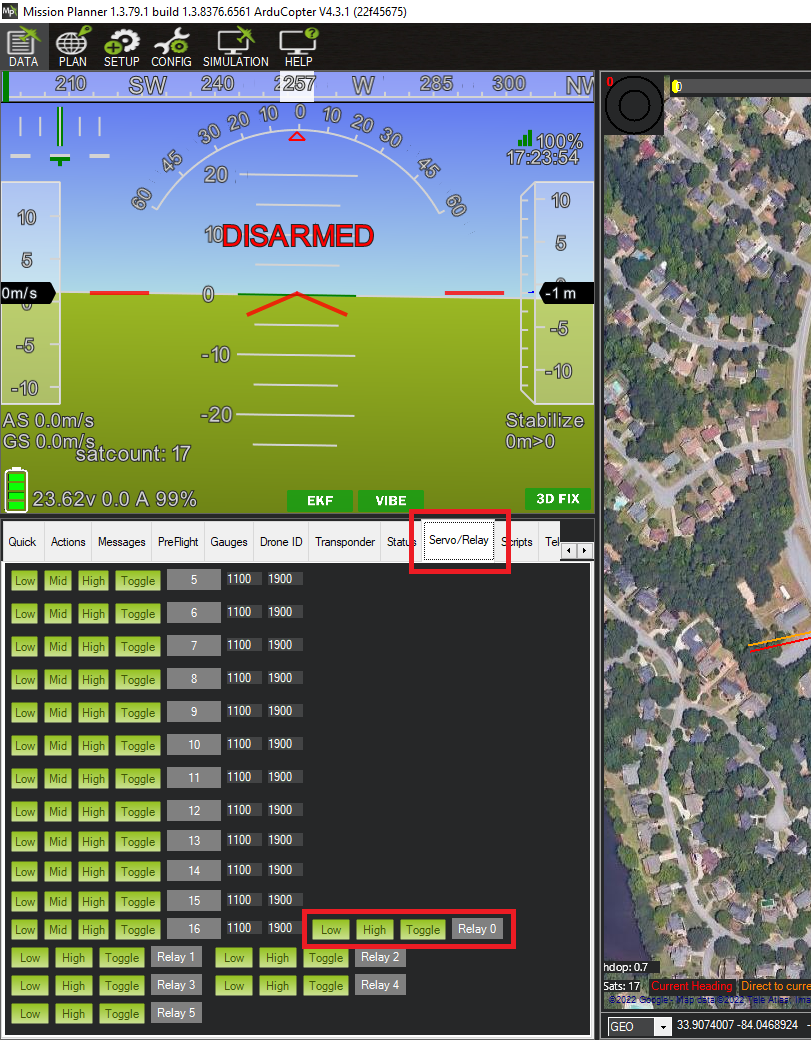
This wiki article also describes the ability of Mission Planner to directly control the relays. This can be useful for testing that the wiring is correct. Note that this screen shows relays in logical order starting with “0”. In my implementation, my relay is the first and only one – so it’s operated on this screen using the “Relay 0” buttons.
From my testing, it appears that relay’s depicted HIGH and LOW states are the states that have been commanded – not what the states actually are.
- Camera Shutter Configuration – https://ardupilot.org/copter/docs/common-camera-shutter-with-servo.html
Although it seems backwards, the last wiki article to review is Camera Shutter Configuration. Following the steps outlined in this article above, no additional changes are required to be set.
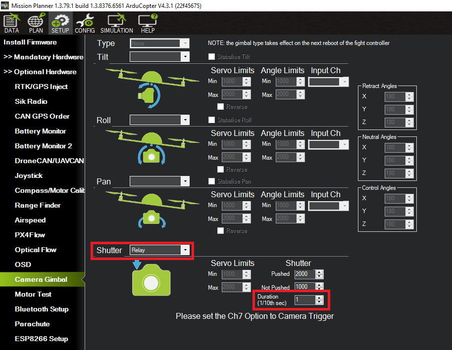
This wiki suggests the SETUP – Camera Gimbal screen. In my case, it displays two parameters I’ve already set – the parameter indicating that the shutter operates with the relay function, and another parameter indicating that relay should be HIGH for 0.1 second to trigger the shutter.
In my case, all other camera parameters are ignored. But it’s good to view this screen to double check that some of the rely parameters were set correctly.
- Enhanced Camera Trigger Logging
The Camera Shutter Configuration wiki article also introduces an additional ArduPilot capability: Enhanced Camera Trigger Logging. This mentions how ArduPilot can read the Hot-Shoe output of a camera to know the precise time the camera shutter is actuated. Without this capability, ArduPilot only knows the time the camera shutter is commanded – and in the length of time between “command” and “actuation” the aircraft may move a significant distance.
I’ve written a companion technical article about using Hot-Shoe input for geotagging. You can link to it here. (in progress)
There is one important clarification about Enhanced Camera Trigger Logging that should be made here. The Camera Shutter Configuration wiki article introduces two messages recorded in the dataflash log files for geotagging: CAM and TRIG.
The description of these messages needs clarification:
- CAM – The dataflash log records CAM messages in two separate circumstances. If a hot-shoe is not used for Enhanced Camera Trigger Logging, a CAM message is recorded in the dataflash log when the camera shutter is commanded. In addition, if Enhanced Camera Trigger Logging is being used with a hot-shoe, then a CAM message is recorded in the log when the camera shutter is actuated.
- TRIG – The TRIG message is recorded in the dataflash log only when Enhanced Camera Logging is being used. With Enhanced Camera Logging the TRIG message logs when the camera shutter is commanded. If there is a failure in the hot-shoe signal, there will be no CAM message associated with it.