It’s been about 12 months since I configured an ArduPilot FFT harmonic notch filter. There have been improvements both in how FFT works and the associated documentation.
The Ardupilot documentation has several FFT related pages that were written for older versions of FFT. Even though the procedures outlined in these older pages are no longer required to use FFT, they describe how to use ArduPilot capabilities that illuminate how FFT is working.
The ArduPilot documentation here provides step by step instruction on setting up a basic FFT dynamic notch filter for a multi-copter.
My article here describes some additional steps – by drawing from the older FFT documentation pages.
I hope the additional information is helpful – both in setting up an FFT harmonic notch filter, and in verifying the results.
First – some background.
FFT stands for Fast Fourier Transform. It’s the name for the mathematics ArduPilot uses to identify the nature of the vibrations experienced by the flight controller’s IMUs..
The job of the flight controller’s IMUs (gyros and accelerometers) is to determine the vehicle’s attitude in space.
The IMUs experience vibration from moving parts such as the motors or propellers. These vibrations may cause the IMU’s to generate false results.
The job of the FFT dynamic notch filter is to attenuate the recognition of such vibrations. This allows the IMUs to correctly determine the aircraft’s attitude.
Second – the process.
Multi-copters experience vibration differently than other vehicles. This article focuses on the multi-copter case.
Vibration will likely be greatest at a specific frequency. This frequency must be identified.
The vibration levels will ramp up and taper off around a central frequency – so the width of the frequency range where vibration occurs must also be identified.
There are likely to be multiple harmonics of the major vibration frequency. Even though these harmonic vibrations are less severe, they too must be attenuated.
The ArduPilot FFT based harmonic notch filter will identify all these vibration values automatically.
The additional steps I’ve included in this article allow viewing the results of the FFT routines.
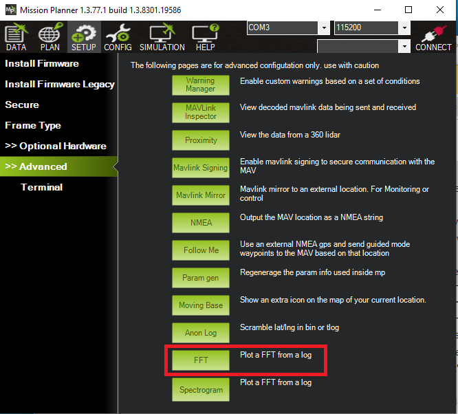
To begin, I think it’s a good idea to first look at vibrations experienced by the vehicle’s IMUs. The ArduPilot documentation describes how to view these vibrations using the “FFT” option that’s available on several Mission Planner screens such as this one:
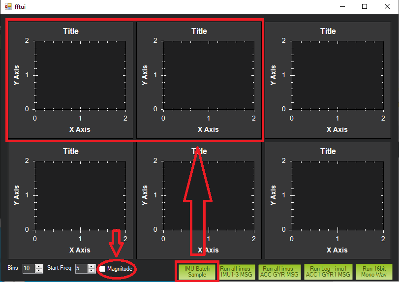
This tool brings up another screen. Clicking the “IMU Batch Sample” button brings up a menu to select a BIN log file. The results are displayed on the first two graph windows.
NOTE: You have to check the “Magnitude” checkbox before selecting the “IMU Bach Sample” button to have the proper graph format displayed.
These graphs will be blank until you set the necessary parameters and collect data with a test flight.
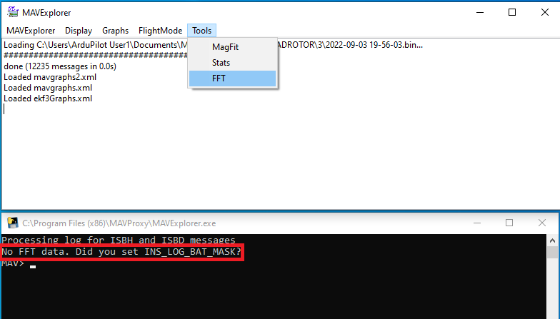
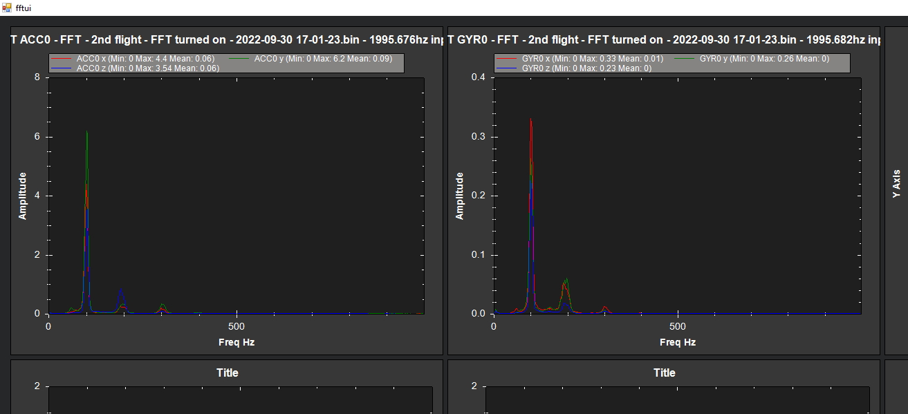
An alternate method is to use the “FFT Tool” option of the MavExplorer utility (a component of MavProxy.)
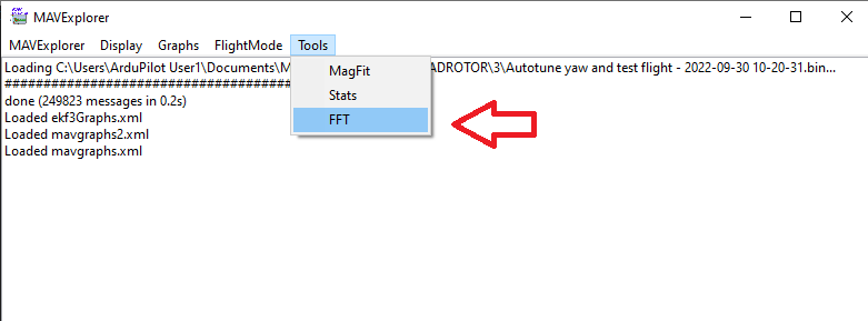
Select a BIN log file with the MAVExplorer drop down menu. Just like the Mission Planner display, this tool requires first setting appropriate ArduPilot parameters and conducting a test flight. Without these prerequisites, the MavExplorer FFT tool will give a message: No FFT data. Did you set INS_LOG_BAT_MASK?
This is one point where the ArduPilot documentation might get confusing. The ArduPilot documentation’s step-by-step instructions don’t include taking a look at vibrations before enabling FFT. But some of the other ArduPilot documentation pages do describe how to do this.
INS_LOG_BAT_MASK is mentioned on this Ardupilot documentation page describing the measurement of IMU vibration. If you want to display and graph the IMU vibration before enabling FFT, you have to select at least one IMU in the INS_LOG_BAT_MASK bit mask and collect data with a test flight.
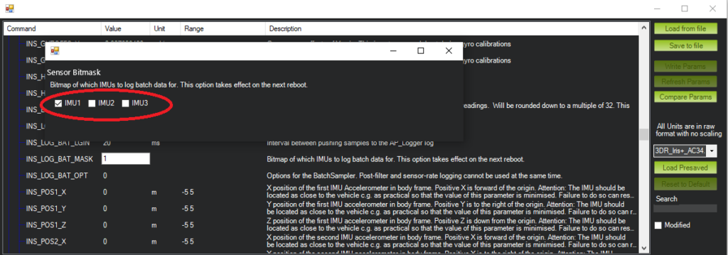
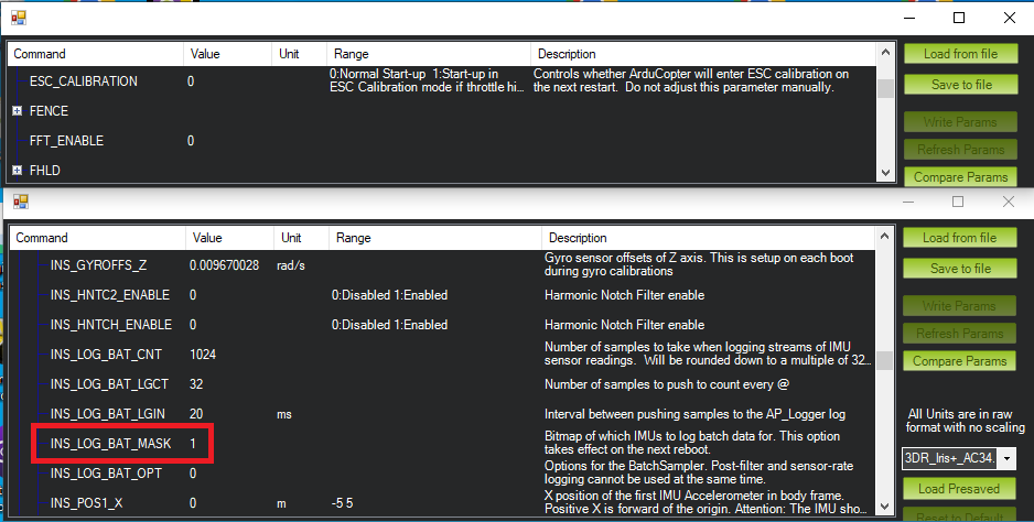
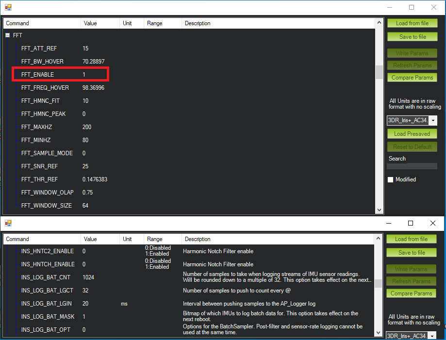
If you only set the INS_LOG_BAT_MASK parameter, the available FFT related parameters will be as follows:
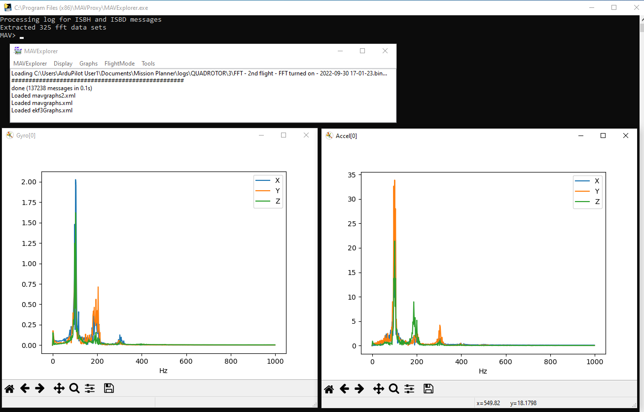
After a test flight with this parameter set, BIN log file will have IMU vibration data that both Mission Planner and MavExplorer can display.
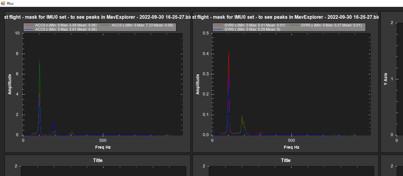
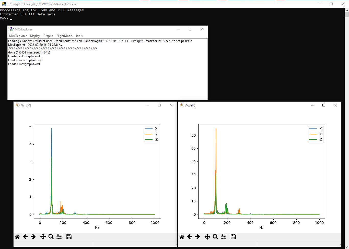
Note that on the MavExplorer grapy, the Y-axis units are not labeled. Comparing with the Mission Planner graphs, the Y-axis units differ by a factor of 10. Either Mission Planner or MavExplorer graphs can still be used to display the “before” and “after” effects of the FFT dynamic notch filter.
Once these charts are recorded for future reference, one can continue with the instructions on the ArduPilot documentation page for setting up the FFT Based Harmonic Notch.
With or without these pre-FFT vibration levels documented, the steps on the In-Flight FFT Based Harmonic Notch Setup can be followed.
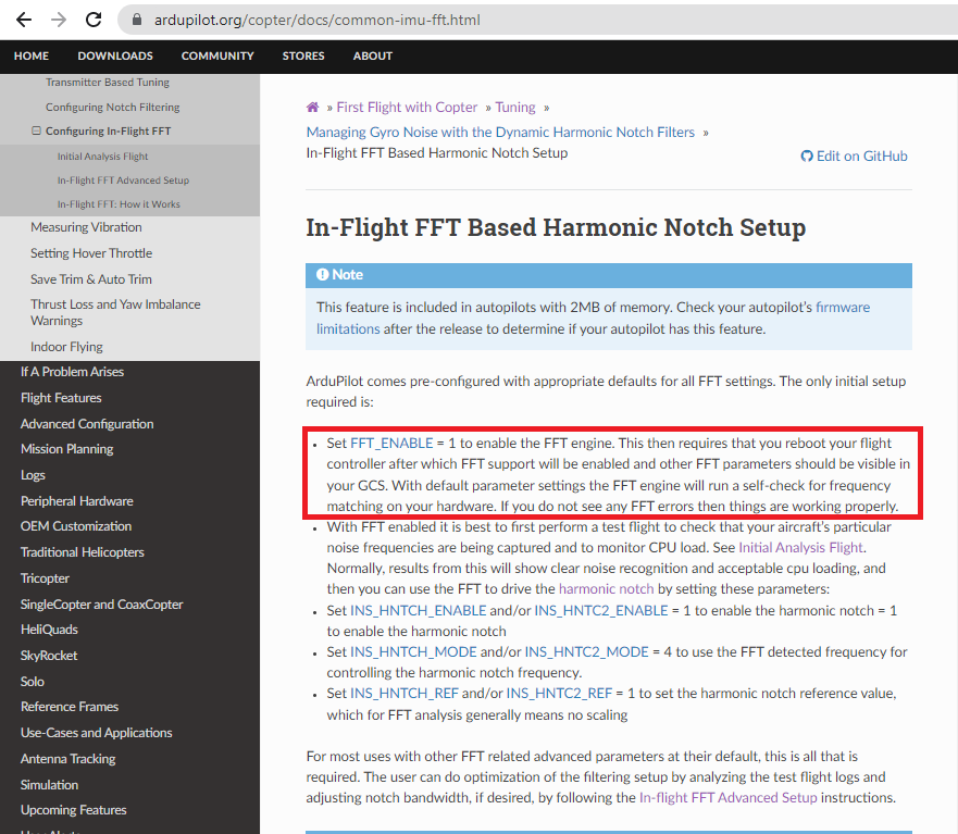
Turning on (or enabling) FFT processing by setting FFT_ENABLE=1 and re-booting does two things. It turns on ArduPilot’s FFT processing. And setting FFT_ENABLE=1 also makes several other parameters FFT related parameters appear.
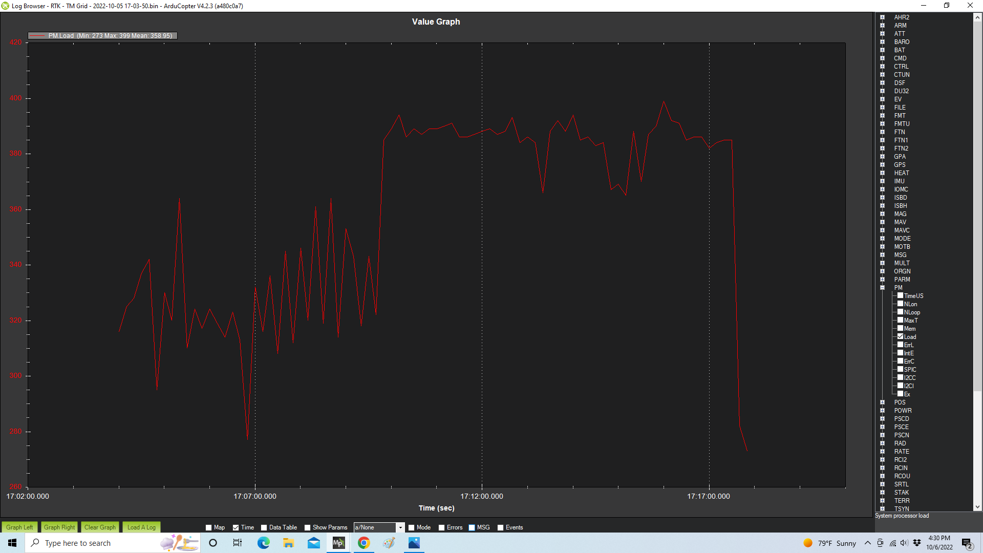
The ArduPilot documentation recommend checking that FFT processing doesn’t overload the flight controller’s processing capability on flights with FFT enabled. It can be checked by charting the PM.LOAD parameter. PM.LOAD can be charted at any stage of setting up FFT parameters – or any other time. The charted processor load values are 10 times the percent of computing capacity. 30%-40% load looks like this:
The ArduPilot documents recommend charting the IMU vibration graphs once FFT is enabled and a test flight is conducted.
Notice that the Mission Planner charts are about the same with and without FFT enabled. The MavExplorer charts however have different Y-axis levels displayed.
The next step is to turn on (enable) the harmonic notch filter by setting INS_HNTCH_ENABLE=1.
Note – turning on an “enable” parameter there may be other parameters that show up after re-booting. If you’re reading ahead and checking the value of parameters used in future steps, you may not find some parameters until all the prerequisite parameters are enabled first and ArduPilot is re-booted.
Then set what kind of harmonic notch filter to use – there are several choices. To select the FFT harmonic notch filter set INS_HNTCH_MODE=4.
The ArduPilot documentation then directs setting “no scaling” for FFT by setting INS_HNTCH_REF=1.
After re-booting and a test flight, the FFT related parameters now look like this:
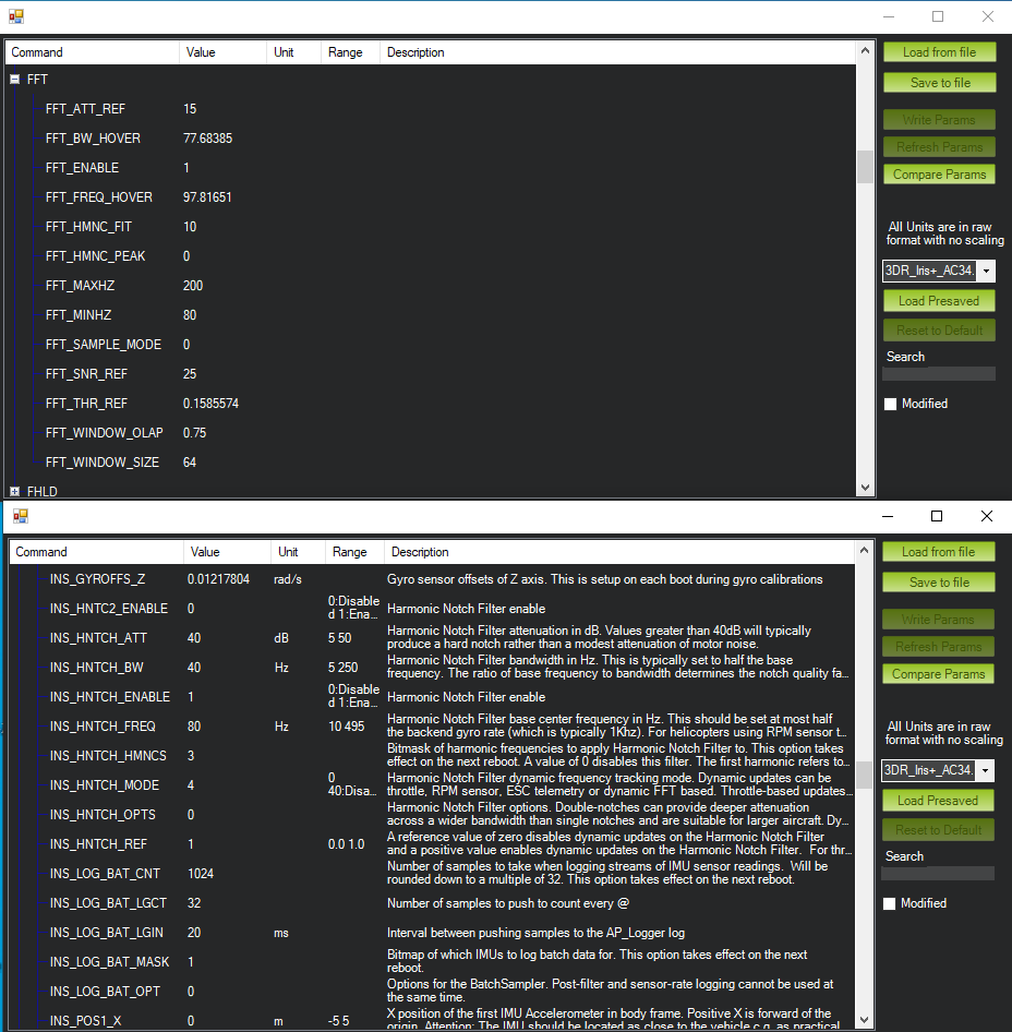
Notice that the key values describing IMU vibration have been automatically determined.
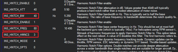
The ArduPilot FFT function has automatically determined three key values:
- INS_HNTCH_FREQ – The main frequency of the IMU vibrations.
- INS_HNTCH_BW – The with of the frequencies on the main frequency.
- INS_HNTCH_HMNCS – The number of harmonics.
The values of these parameters match the graphs shown in the vibration graphs.
With the FFT and harmonic notch parameters set, it is now possible to graph some of these values to better display them. For example, FTN1.BwAvg shows that the vibration centers around 80Hz, and has a bandwidth of roughly 40Hz. These values are accurately stored in the parameters INS_HNTCH_FREQ and INS_HNTCH_BW shown above. The number of harmonics stored in INS_HNTCH_HMNCS matches the number of peaks shown in the MavExplorer vibration graphs above.
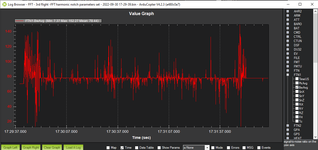
Analysis such as this is described on this Ardupilot documentation page.
At this point the FFT harmonic notch filter is working. To verify that it’s working a test flight must be flown with the “post-filtering” vibration data collected.
To collect the post-filtering vibration data the INS_LOG_BAT_OPT parameter is used. If you don’t use this parameter to collect “post-filtering” data, the vibration graphs will continue to display the vibration levels before the FFT harmonic notch filter attenuation is applied.
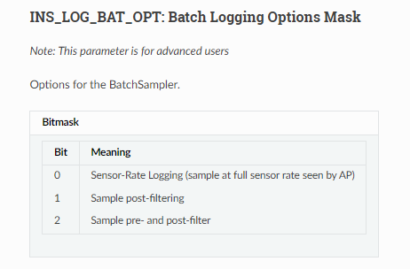
By setting INS_LOG_BAT_OPT=1 and conducting another test flight, the reduction in detected vibrations can be displayed in both Mission Planner and MavExplorer.
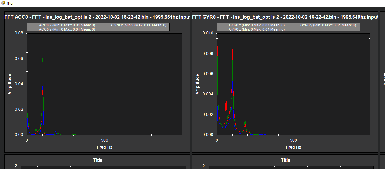
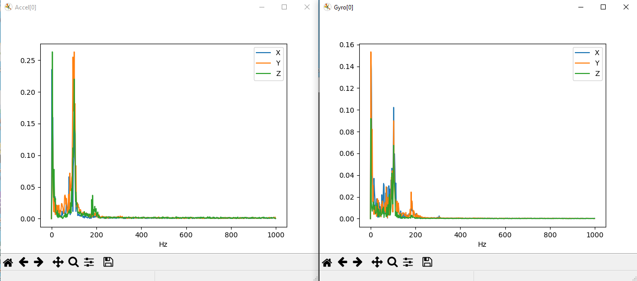
Compared with the graphs showing IMU vibration before enabling FFT the MavExplorer shows accelerometer vibration detection dropping from about 2.0 down to 0.25. The reduction detected gyro vibration drops from about 35 to 0.15.
It’s not required to do this check in order for FFT to be working. In fact, to reduce CPU load, INS_LOG_BAT_OPT can be reset to 0.
Here’s the CPU load for my copter when INS_LOG_BAT_OPT is set to keep the FFT result values:
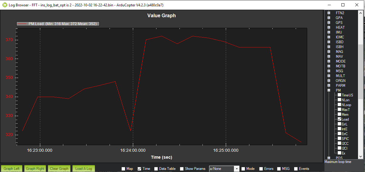
The CPU load on my Orange Cube is a little bit higher with all the post FFT data recorded, but it never gets higher than 40%.
Another recent feature is the presentation of FFT parameters on Mission Planner’s Extended Tuning screen:
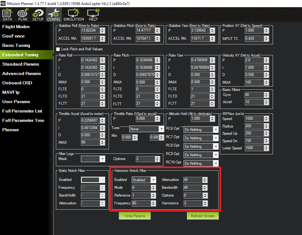
I haven’t found documentation yet on how these Mission Planner options work. It may be possible to use this screen to set up FFT processing from the beginning. I’ll try that on my next project.
This concludes this article. I welcome comments, corrections and constructive criticism.
I am using MP version 1.3.77 but do not have the Magnitude check box option on the fftui pop-up window. Also, the MAVproxy tool does not work on my computer. It crashes. Probably because I am using windows 11.
When I first did FFT there was not “Magnitude” check box – and without it, it displayed the proper graph – similar to the MavExplorer graph. I don’t know if my copy of Mission Planner has the “Magnitude” check box because it’s a newer version than yours, or because I’m using the latest beta. Regardless – since you don’t have the checkbox, I suspect you’re getting the right graph.
MavExplorer is very useful – in particular it’s MagFit utility. I’ll probe to see if there’s a problem with Windows 11.